

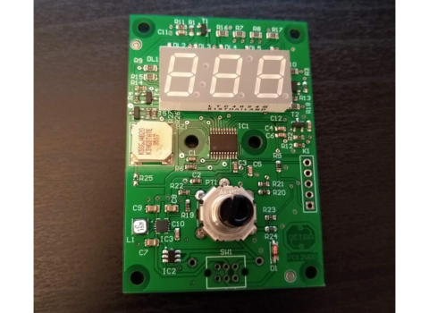


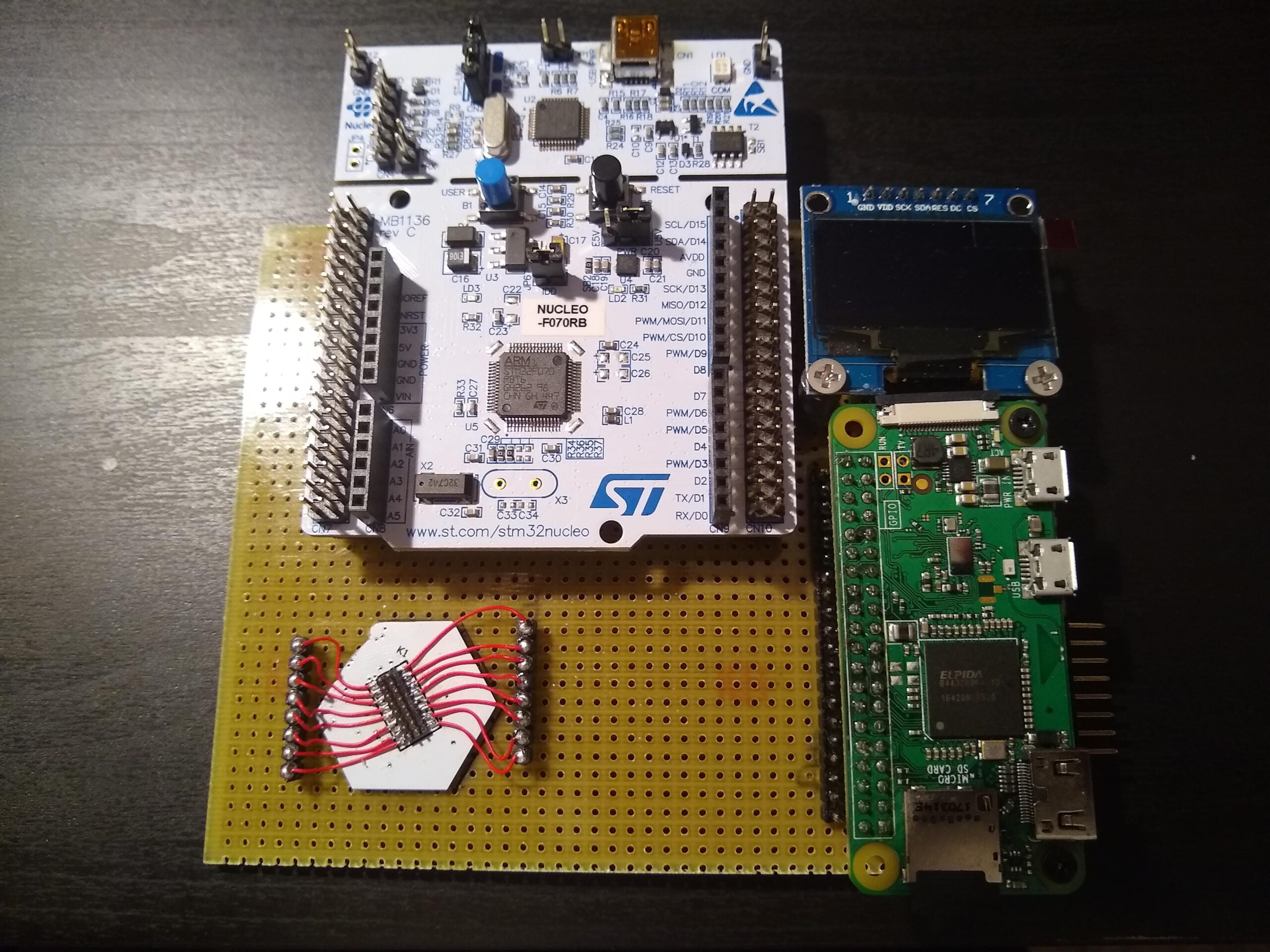
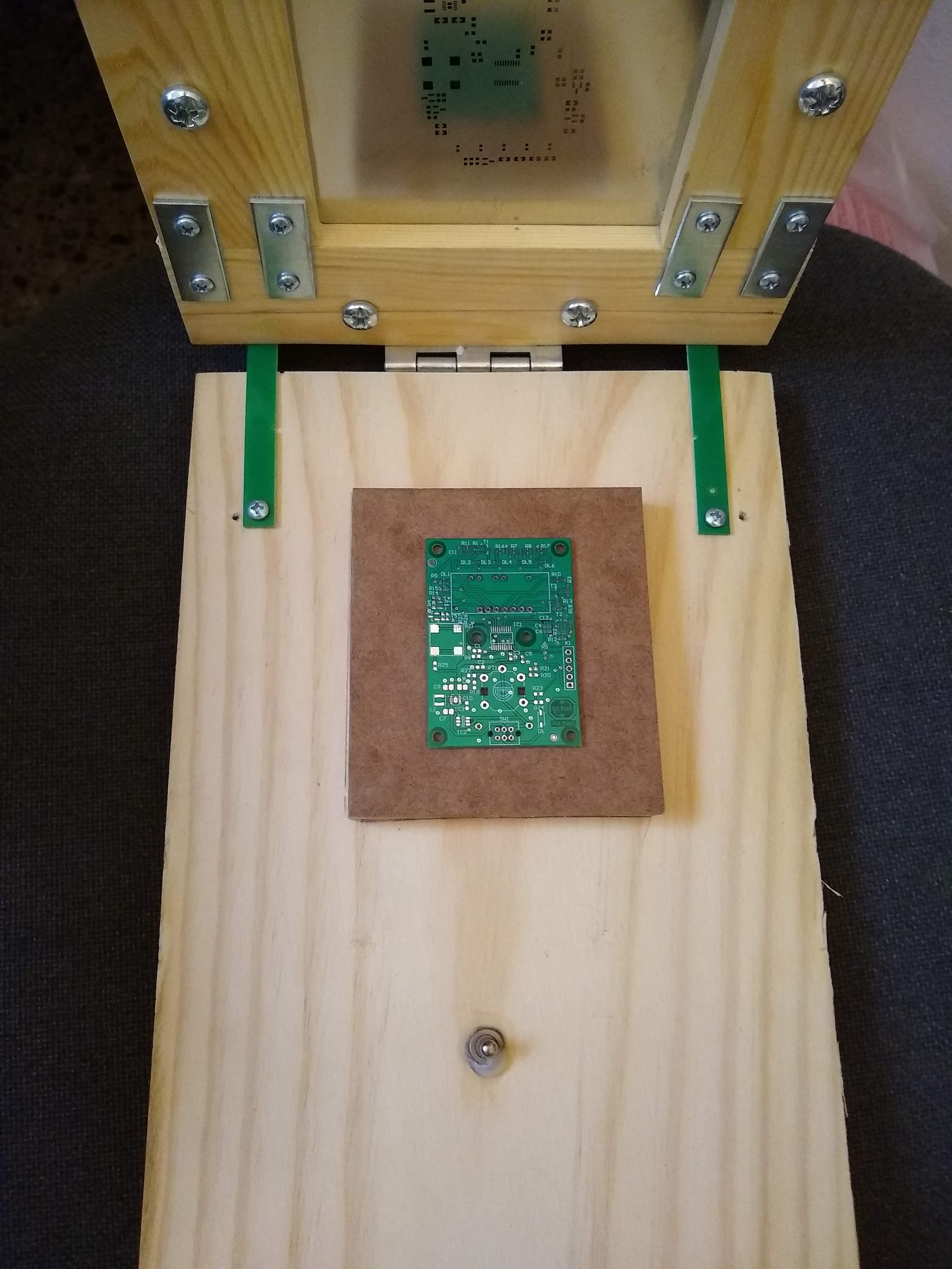
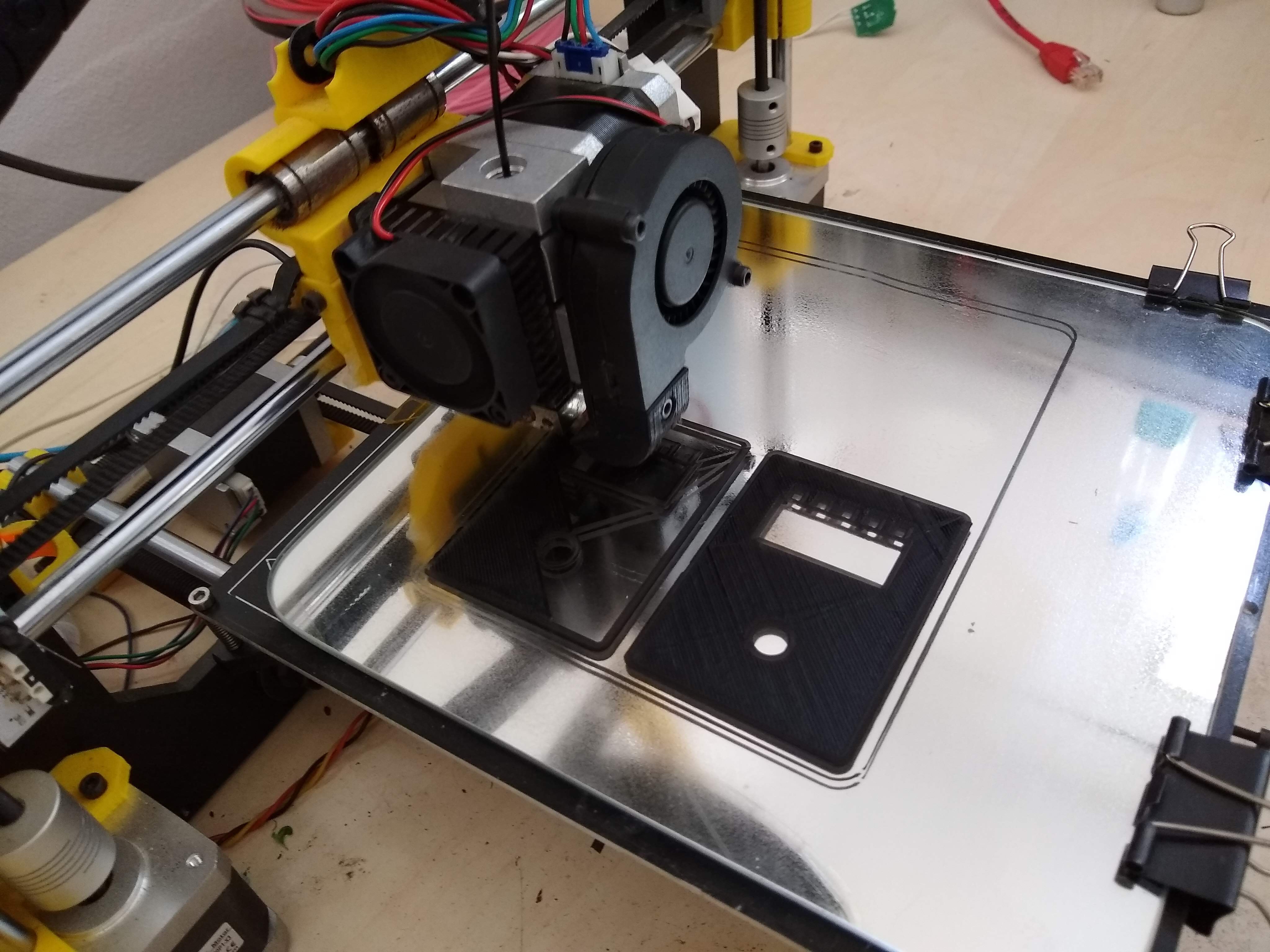
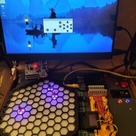
Assembly of the prototype of the ZeroDeck interface.
I have finished assembling the ZeroDeck interface to be able to control the game boards that I design. Separating the game board from the player interface allows me 2 things, first I can design the board independently of the interface and so you can control it by USB with a standalone module like the ZeroDeck or connect it to a PC or you could even connect it to a mobile and control the board from it. And second, the ZeroDeck interface can evolve independently of the board and serve for several different boards.
The current Helvetios board is just a prototype with which to design the development infrastructure and test the technologies involved. In the future the board will grow in size and number of cells, but first I have to test that everything works correctly, it is even possible that there are some rectangular or with another shape.
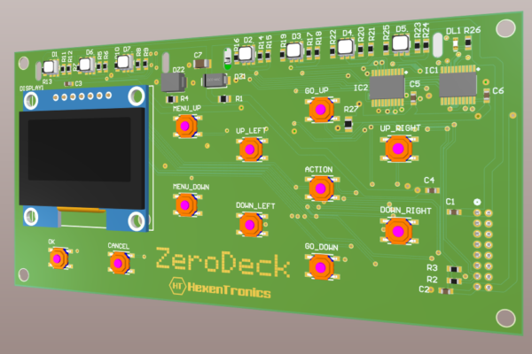
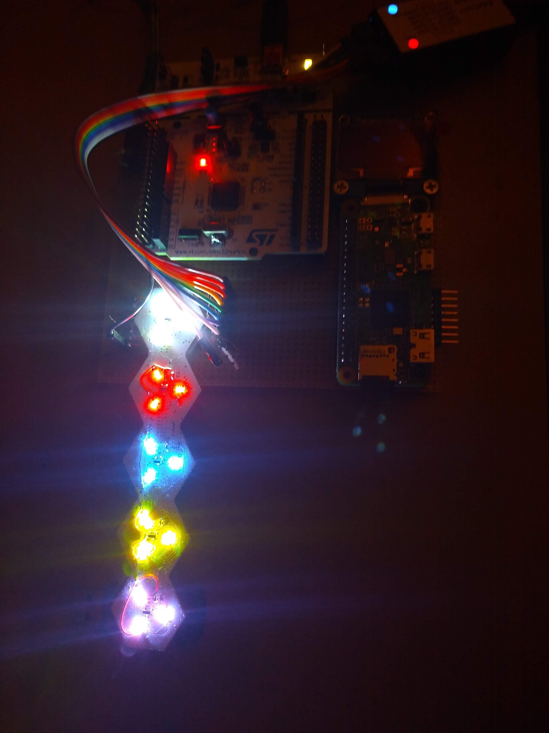
For now with this interface I can develop more easily. Until now I used an RPI4 to connect it to the board and with a GPIO pin expansion circuit I connected a keyboard and an SPI OLED screen. Now I have the GamMa game program running on an RPI Zero 2W that controls the screen, reads the buttons and turns on the LEDs that will indicate the player’s status/turn and what phase of the game they are in. The assembled circuit is as follows:
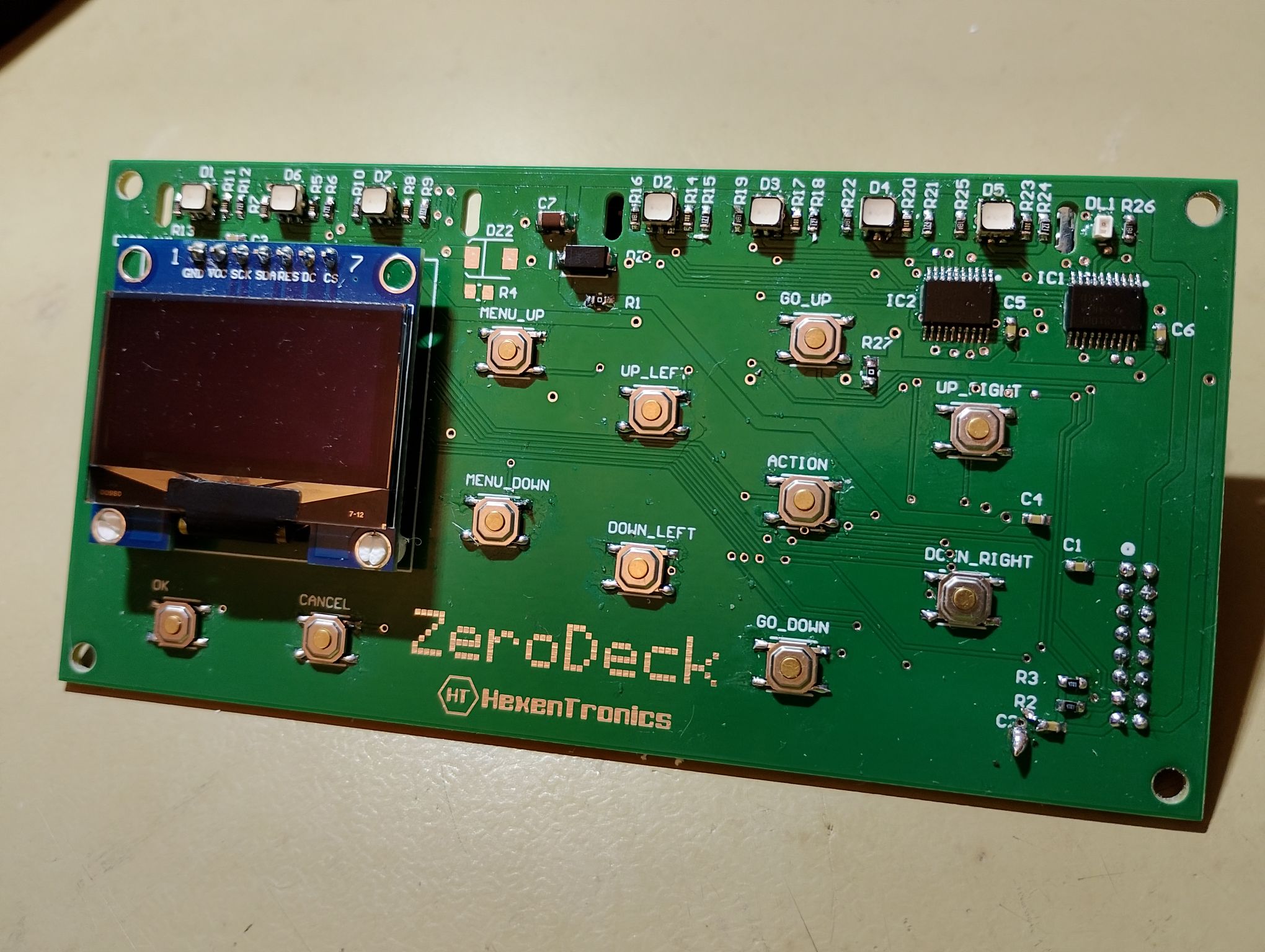
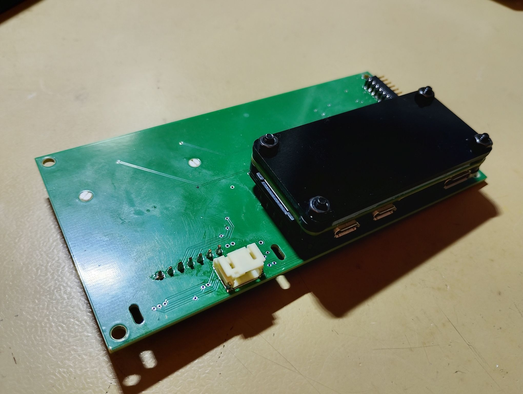
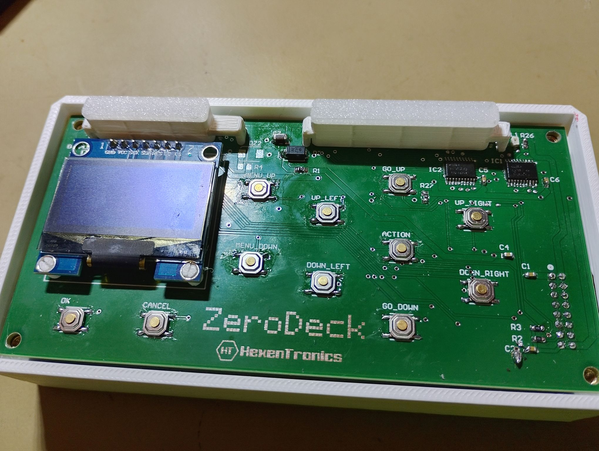
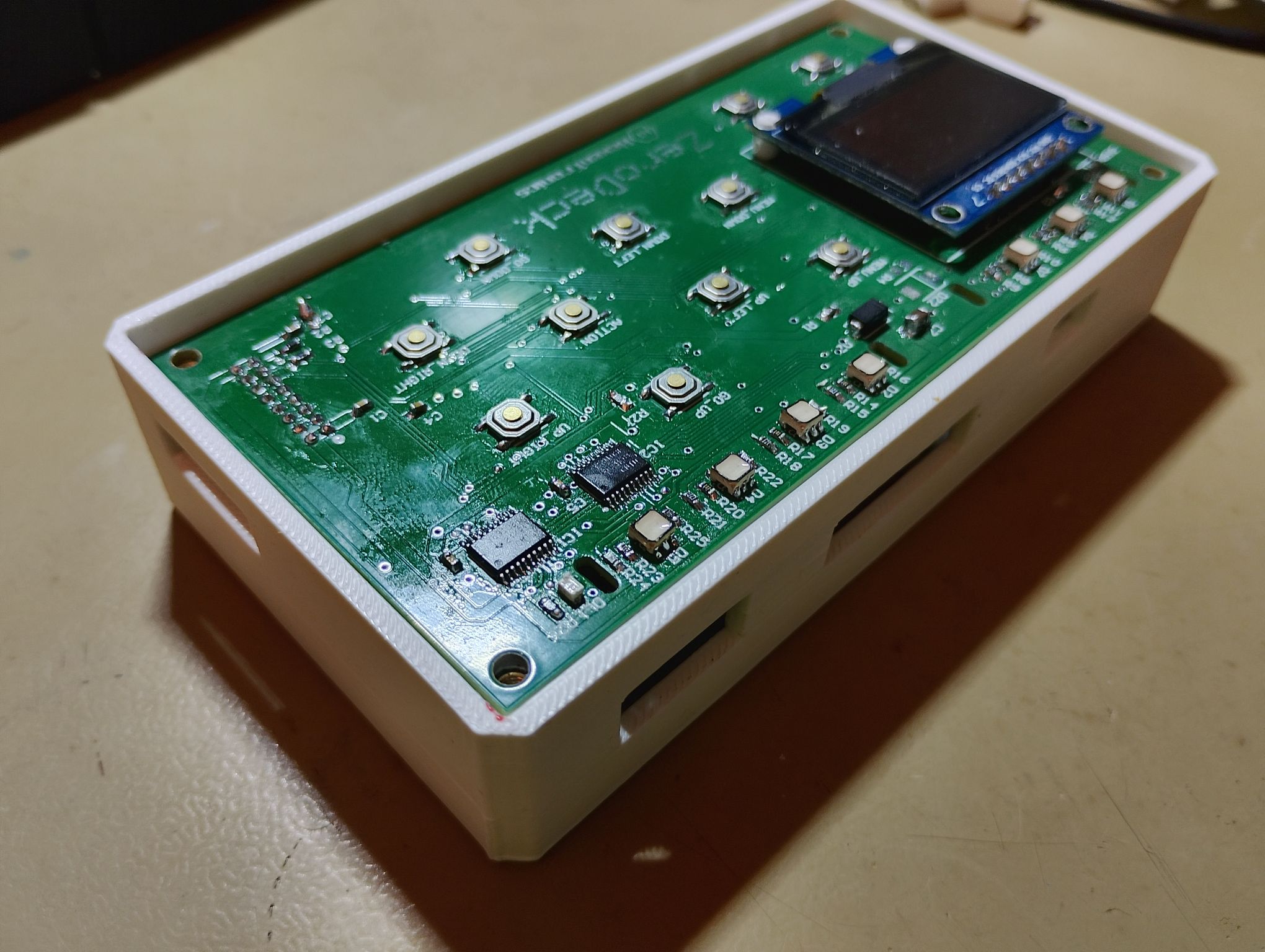
The Zerodeck’s connector openings allow access to the RPI Zero’s microUSB and mini HDMI connectors. It also has its own power connector, since it can be fed directly from the boardgame with a cable designed for it and thus only have one power supply for the whole set. The circuit has another side connector that will allow it to be expanded and tested with other circuits. The idea is to be able to connect a second or several identical modules for each player, and having only one ‘Master’ module with the RPI Zero that controls the rest of the interfaces. It also has to be used to test other modules that I have in mind, such as an NFC tag reader so that each piece can save its statistics and characteristics, and perhaps a small sound module for some effects.
For now, the first tests are as that:
The use of an RPI Zero has a handicap and that is development. In order to develop the GamMa application for control of the board I have been using VSCo remotely in the RPI4 with good results to interact, debug and compile. Not so with the RPIZero, because it does not have an ethernet connection and through Wi-Fi VSCode’s remote mode does not seem to work very well, with multiple interruptions. Debug and compile also don’t work very fast in the RPIZero, so I keep developing in the RPI4 with VSCode and when I have a change ready I synchronize them through Github in the RPIZero, where I recompile it, since they have different cores. For now I’ll have to develop like this, maybe I’ll try automating it a little more or using NFS.
Interface ZeroDeck for RPI Zero
In this project I have been programming at the beginning an interface in GTK called GamMa. But the goal was to run that application on an RPI Zero 2W and for it to communicate with the dashboard via USB and serve as an interface with the player. During the development of the GamMa application I have been changing the development method and adapting the code as I found problems and learned more to program in C++.
I started the application using Geany as an IDE, which was the one I had used until then to develop in a RevPI, since it was very light and easy for me who had always programmed in C for microcontrollers. To make some progress on this topic I switched to Codeblocks, which is more designed to work in C++ and also runs correctly on an RPI4.
Then I learned how to use Visual Studio Code with the Remote SSH plugin, which allowed me to easily work from my PC without having to run a remote desktop on the RPI. Since then I have developed like this, and I have been adapting the code as I found problems.
The first problem was with the USB access libraries. I started with HIDAPI, but due to problems in compiling for ARM I switched to LibUSB. Once I had the dashboard communicating via USB with the GTK interface, I discarded this interface to focus on developing a physical interface with buttons and a 128×64 SPI OLED display. For this I used WiringPI but I also ended up discarding it due to problems when integrating the library to control the screen. I then used the bcm2835 library that allows access to the gpio, the I2C and the SPI.
The library to control the screen is ArduiPi_OLED, which is an Arduino ported library to make it work in RPI. I had to modify it to be able to include the SH1106 OLED controller in SPI mode and added some more functionalities such as word-end detection and corrected errors to be able to better integrate it into the project. This is my fork: Fork ArduiPi_OLED. It is possible that it will recover the GTK version if it evolves enough to require an application on x86 or on an RPI with an LCD, but for now I will develop it this way, with a physical screen and keyboard.
The game menus in the prototype currently look like this:
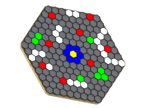
The game right now has a couple of phases, the one in which the player must position the pieces and the one that allows the player to decide the movement of their piece. The player’s starting position is always the same, but that of the target (asteroid) and enemies (aliens) is randomly generated. Here’s an example of random position generation:
In the player phase, the cells around the player light up indicating your range of movement:
These are the pieces that I have printed to try, they are not the final ones but they are an idea of what they would be like. They have a translucent base and a small magnet for the Hall sensors in the cells to detect them:

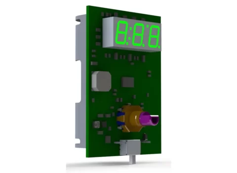
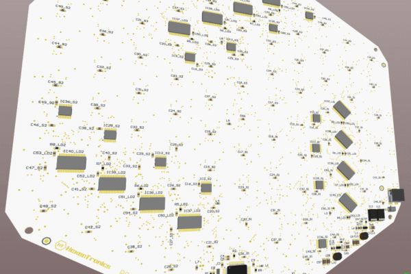
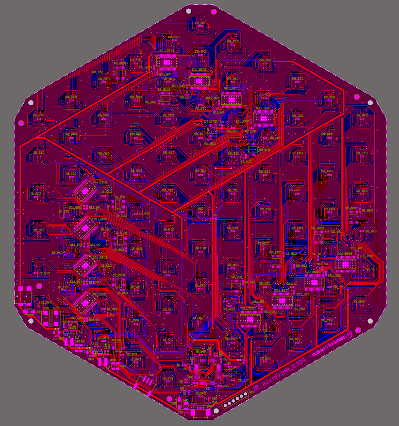
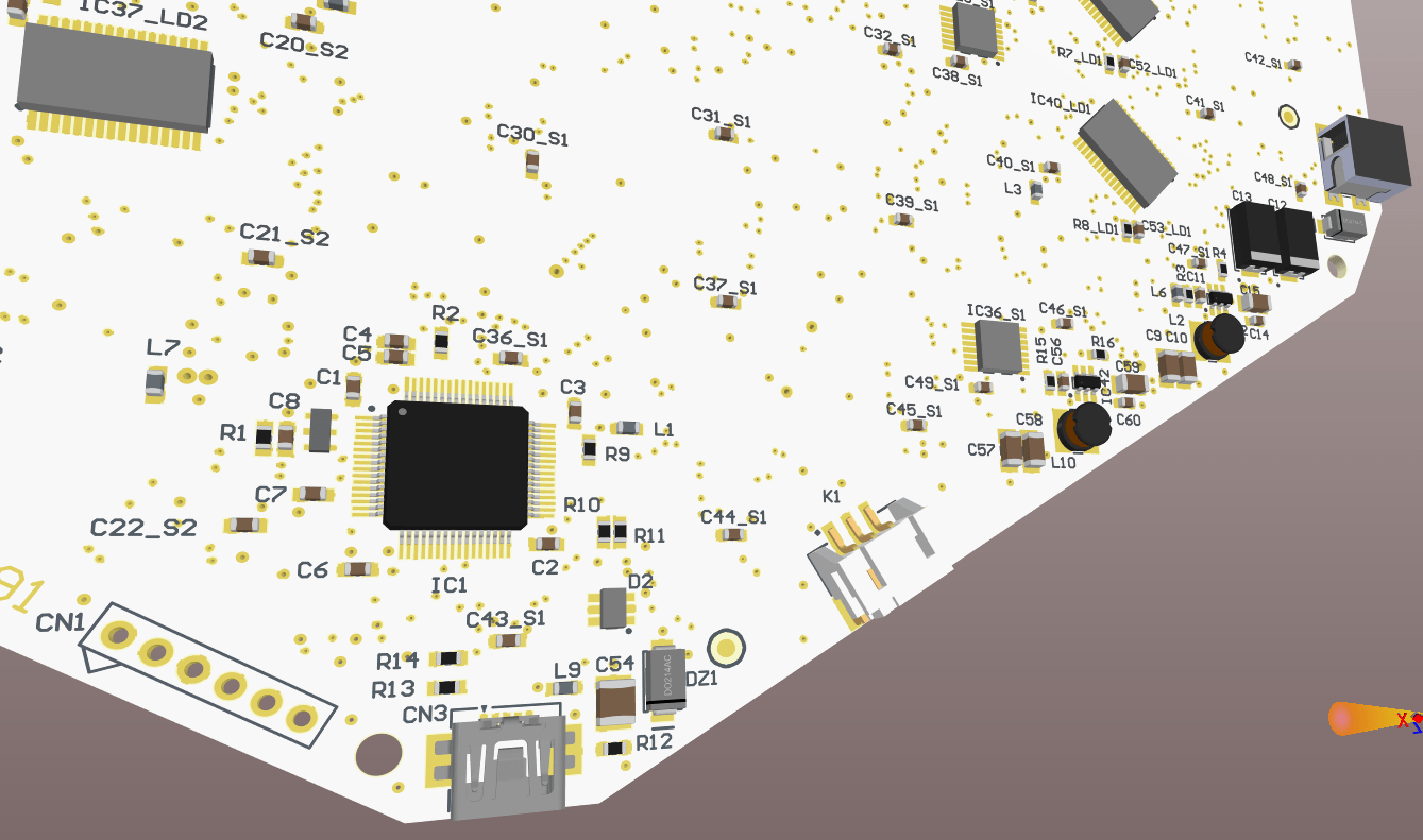
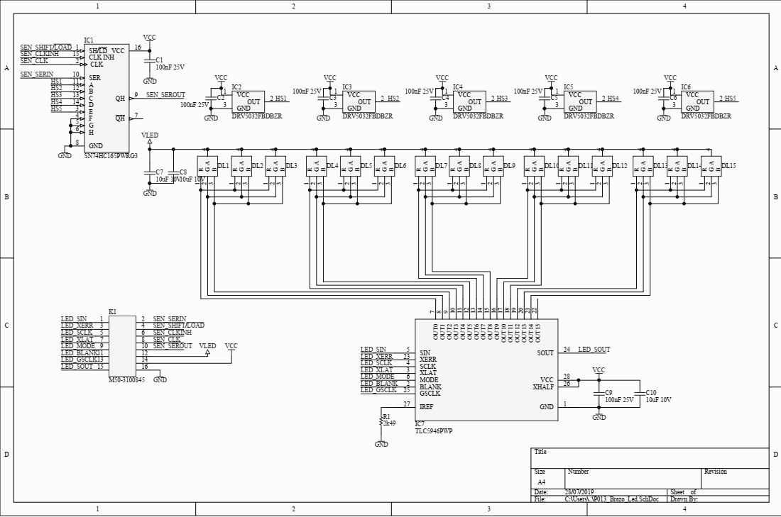
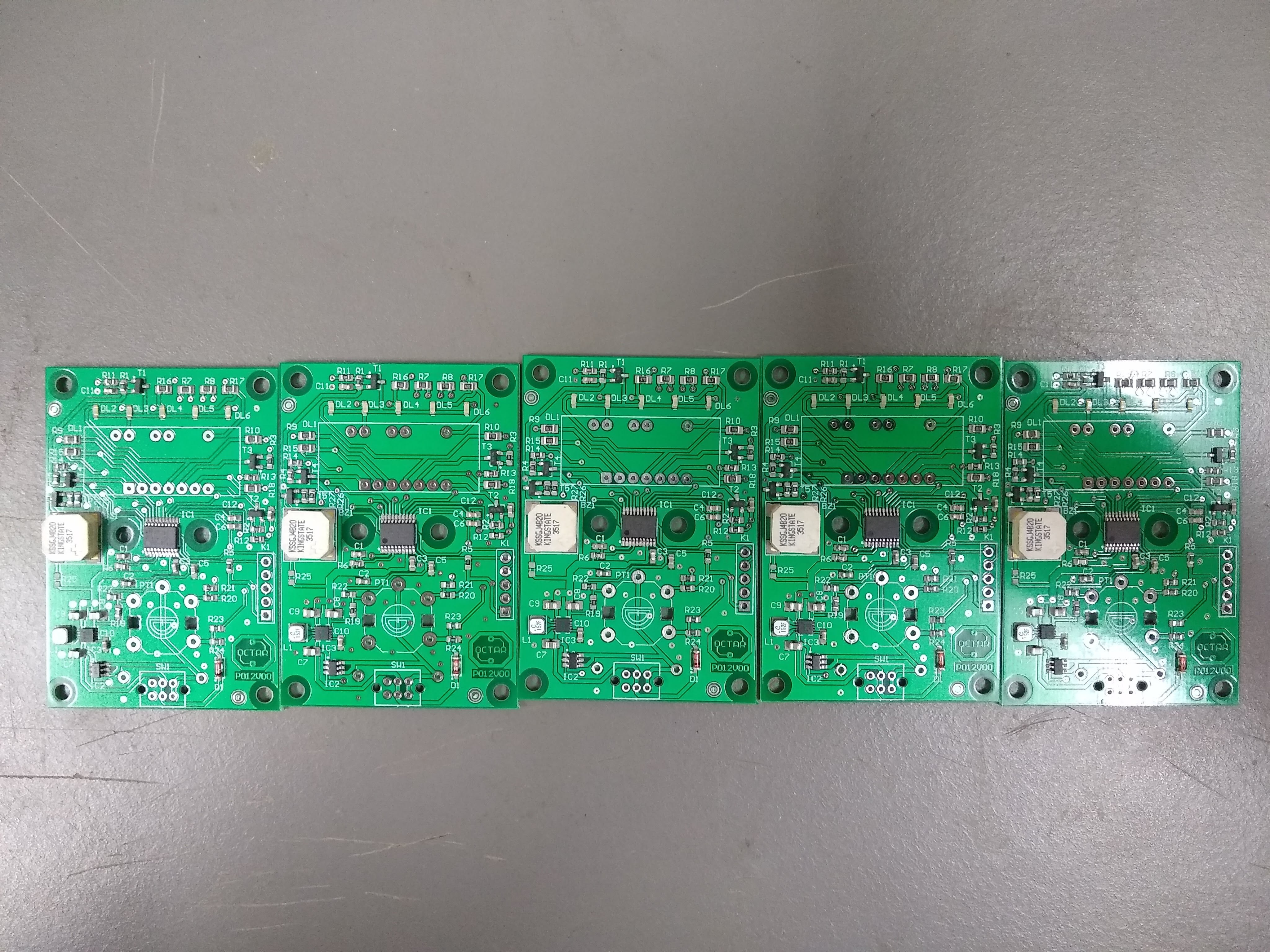
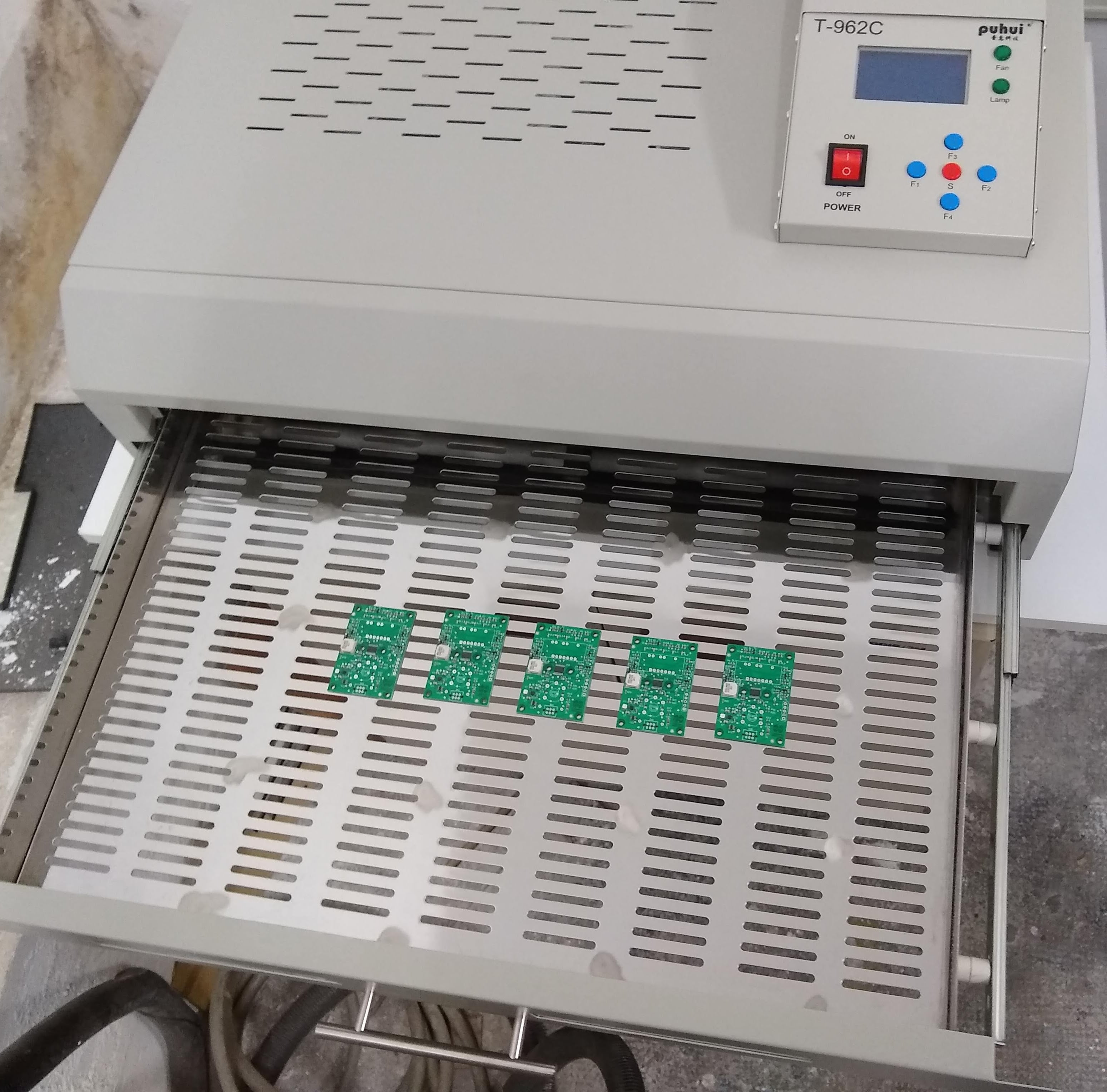
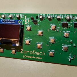
So once I had the prototype working with the connection to the OLED and the buttons, I designed a circuit that would integrate everything and also have the connection for the RPI Zero 2W that will host the GamMa application and communicate with the board via USB. This circuit is designed to be powered from the board itself, which is the one that has the 5V and 3.3V power supplies. It includes the SPI OLED screen, the connector for the RPI Zero, RGB LEDs to indicate the player’s status and the current game phase, and an auxiliary connector that will allow you to expand the functionalities by connecting an NFC reader or another interface for a second player. The circuit diagrams are these:


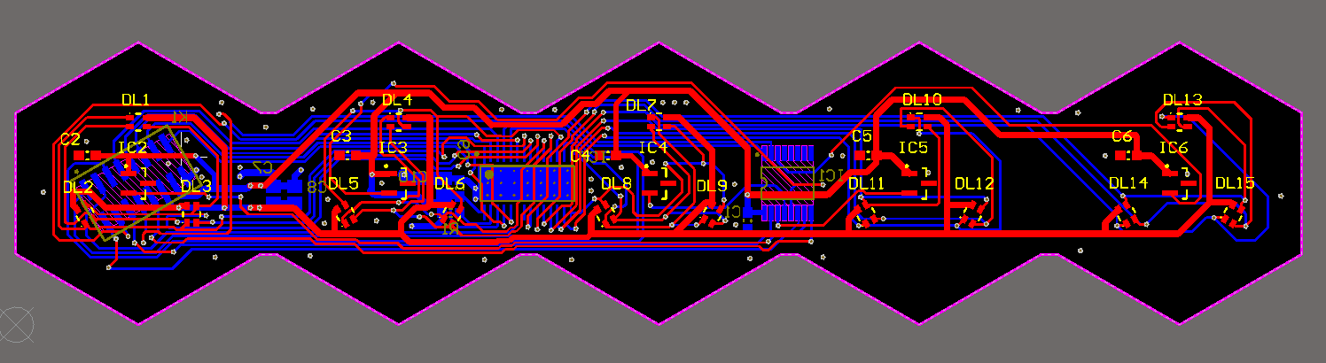
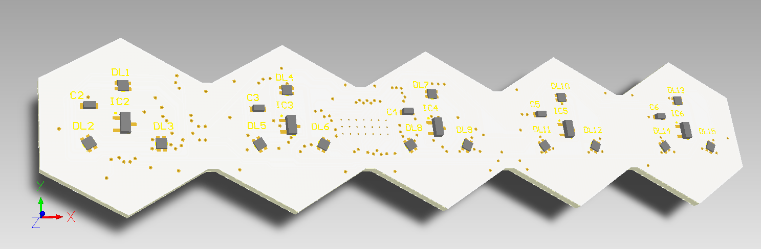
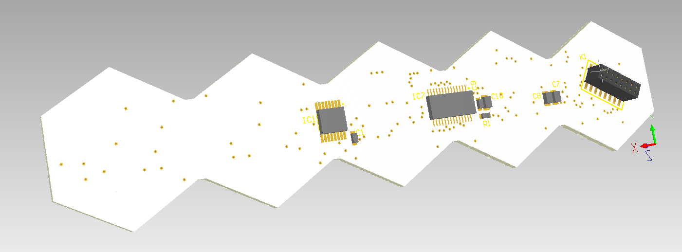
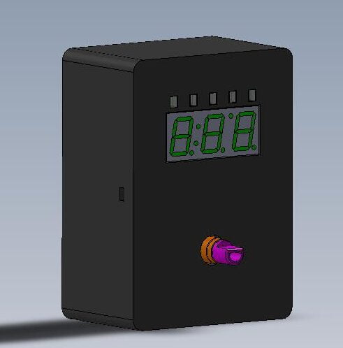
And the renders of the circuit are such as this:


The circuit design, schematic and bill of materials can be obtained from PCBWay, as well as order the pcb directly. This design is open, anyone can use it for whatever they want, but the GamMa application is not yet published until I get a minimum operation and see which license I choose.
USB communication with the boardgame and the GamMa program.
I’m already working again in the project after a long pause, but with renewed strength. I’ve mounted the Helvetios boardgame in a trainer that I made some time ago: a briefcase with a RaspberryPi, an LCD screen, some batteries and a power supply system. This way I can develop the software to control the boardgame without connecting a computer. The project for this briefcase can be checked in Hackaday.

In this trainer I’m developing the application GamMa (Game Master) to manage the electronic boardgame. Its a C++ application, not because it’s needed but as a way to improve my skills in this language, that I don’t usually use in my projects. It could be done in C or Python without issues.
This program will manage the communication with the boardgame and to work as an interface between the player and virtual ‘Game Master’. This Game Master will be the code that will guide the player in the actions to take in each game phase (move, defend, attack, collect, mine, trade, etc…) and will show the consequence of these actions. That will be done using a screen where it will show the options of each phase and also in the board by illuminating the cells affected by the range, direction or target selected by the action. The player also could select the action with the selection, accept and cancel buttons, and has a navigation panel with 6 buttons to select the range or direction of this action. A simplified version of the interface will look like this:

Right now this program only communicates by USB with the boardgame, being able to control the color of the cells and read if there is a piece in any cell. It will also manage the flow of the game between various players and decide the result of the selected actions of each player based in some prearranged rules, assigning by the parameters of each piece or player as speed, energy, strength, range, shield, load capacity, goods pricing, etc…
It is intended that all text, actions and rules are programmable and editable externally to the code, so that the games can be fully adapted to a story and turn the board into a collaborative playground or battle as set in the configuration by the user without programming knowledge. This way we can set up multiple games on each board, totally changing the story and the objectives of the game, being able to be a game of asteroid mining, resource gathering, tank battles, ships, boats, soldiers, orcs, space marines…, or simply abstract logic games or puzzles. Everything is up to my ability to program the game logic and the editing system of menus, phases and rules.
The code of this application uses the HidAPI library to communicate with the board, with a more than acceptable speed for the intended application. The STM32F103 microcontroller is capable of handling a 12Mbits FS USB connection, but there is a lot of overhead in the USB protocol and the effective speed is considerably lower. However, based on tests it is more than sufficient to transmit a cell status update. The animations will be programmed and executed on the microcontroller side, leaving free the communications for state updates (cell color and animation, piece detection in each cell). This application will be available in my Github, so it can be used by anyone as a base to develop other interfaces or modify it to include other functionalities.
The representation of the interface is made with GTK3, which is light enough to run on any system, as well as the C++ code will also be fast enough without needing much processing power or memory, if it were developed in Python or QT surely the resource consumption would be higher. A simple GTK interface will be developed so that the board can be connected to any Linux computer or embedded system, but the goal is to recreate a hardware interface for each player on the board. That is: various OLED screens of 128×64 pixels, if required a larger one will be used, a button panel for menu and board navigation, a led bar that identifies the turn or status of each player and some leds that identify in which phase of his turn he is:

This way the board is independent of a computer, and using a low-resource embedded system such as the Raspberry Pi Zero 2W would be sufficient to control several of these player interfaces for the same board. And with more advanced development, this embedded system can act as a rival to play solo games, connect to the internet to play with multiple boards and remote games with other players. It would also allow a much more advanced game status interface through a web server and show the development or even to interact with the board from a mobile device with a player interface via web.
In addition to what is described for each player, it is intended to include an NFC reader to identify the tokens (meeples, ships, soldier, etc.) of each player or to read cards. In the manufacture of the tokens, an NFC tag such as the Murata micro tag can be inserted. In this way the token itself can gain skills or change characteristics, and this evolution can be registered in the token itself, being able to use these improvements in following games. It has also been thought to include a small speaker that can generate some sound effects of resolution of the actions (battle won/lost, resource obtained/spent, movement, etc…).
And here is a small demo of the USB communication with the board:
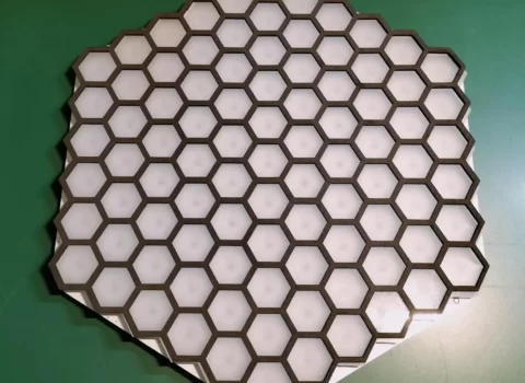
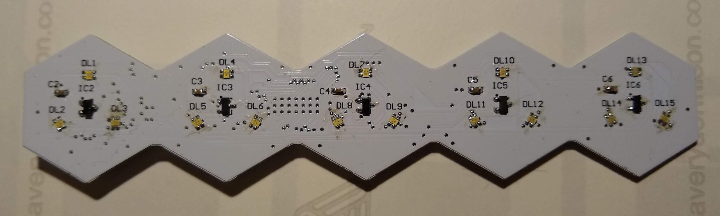
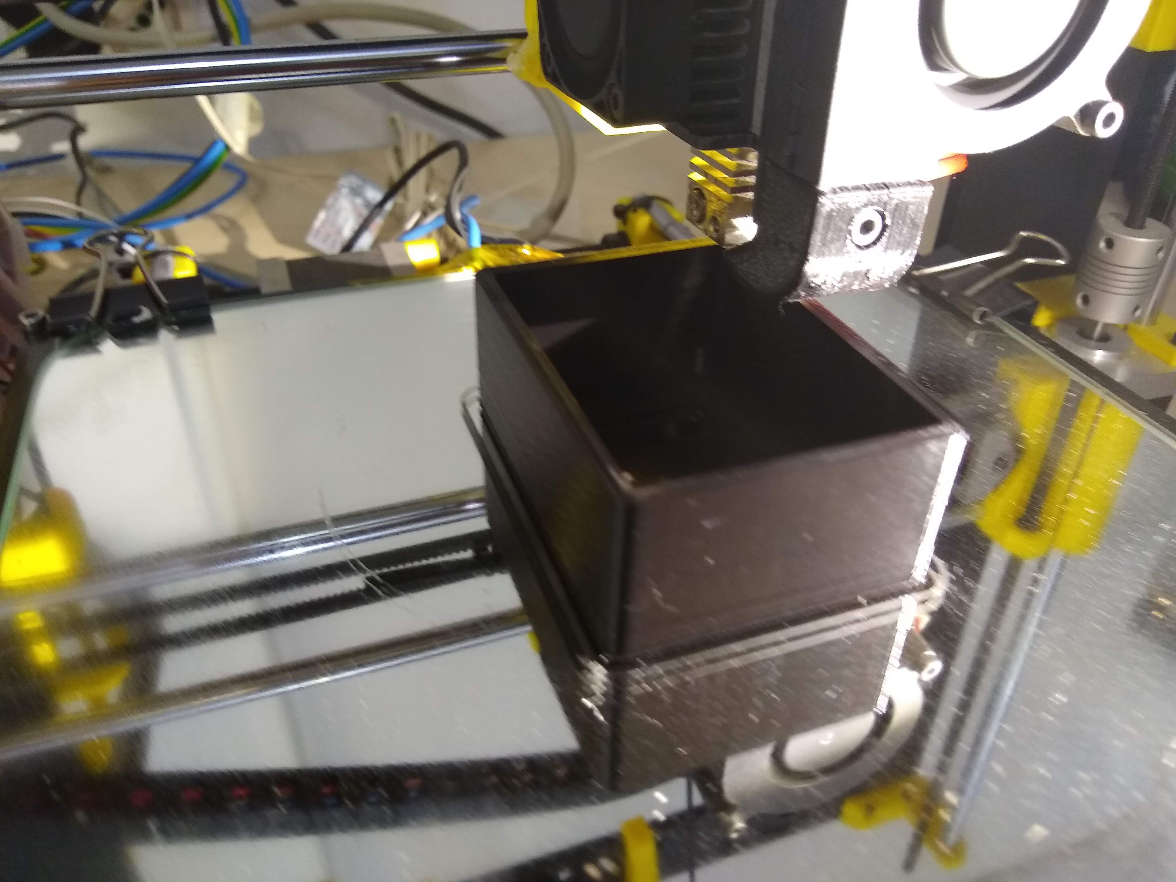
Mounting the prototype of the 91 cells electronic board game
Finally I’ve gathered all the components and mounted the first full prototype of the board game (I already did some test previously to validate the SPI led drivers in First prototype of the electronic board game Helvetios). The component shortage has delayed the mounting by 6 months until I’ve got some critical components, mainly the led driver TLC5947 and the DC/DC regulator TPS561201.
Initially I contacted some pcb companies from China to fully build the prototypes, but the cost of the components at the start of 2022 was way too much. So I ordered only the PCB and the bottom stencil in JLCPCB, and then I gathered the components until have them all so I could build the circuits by myself.
I did the mounting by hand (in the absence of an SMD oven as the I used for the circuits in the LifeLinker), using soldering paste, a hot air soldering station and a lot of patience. To solder the bottom side I used a stencil so it’s were there are more integrated circuits and some with thermal pads like the led driver. This way the solder paste distribution would be much better.
The circuit was designed to be content in size so the first prototypes would be more economical due the pcb price and the necessary acrylic sheets to make the led difusor and the cell separator. This way we could program all the firmware to control the leds and the USB communication. The next designs will follow the concept of row circuits as explained in Helvetios. This way we could make boards with more and bigger cells.
Some pictures of the mounting process:


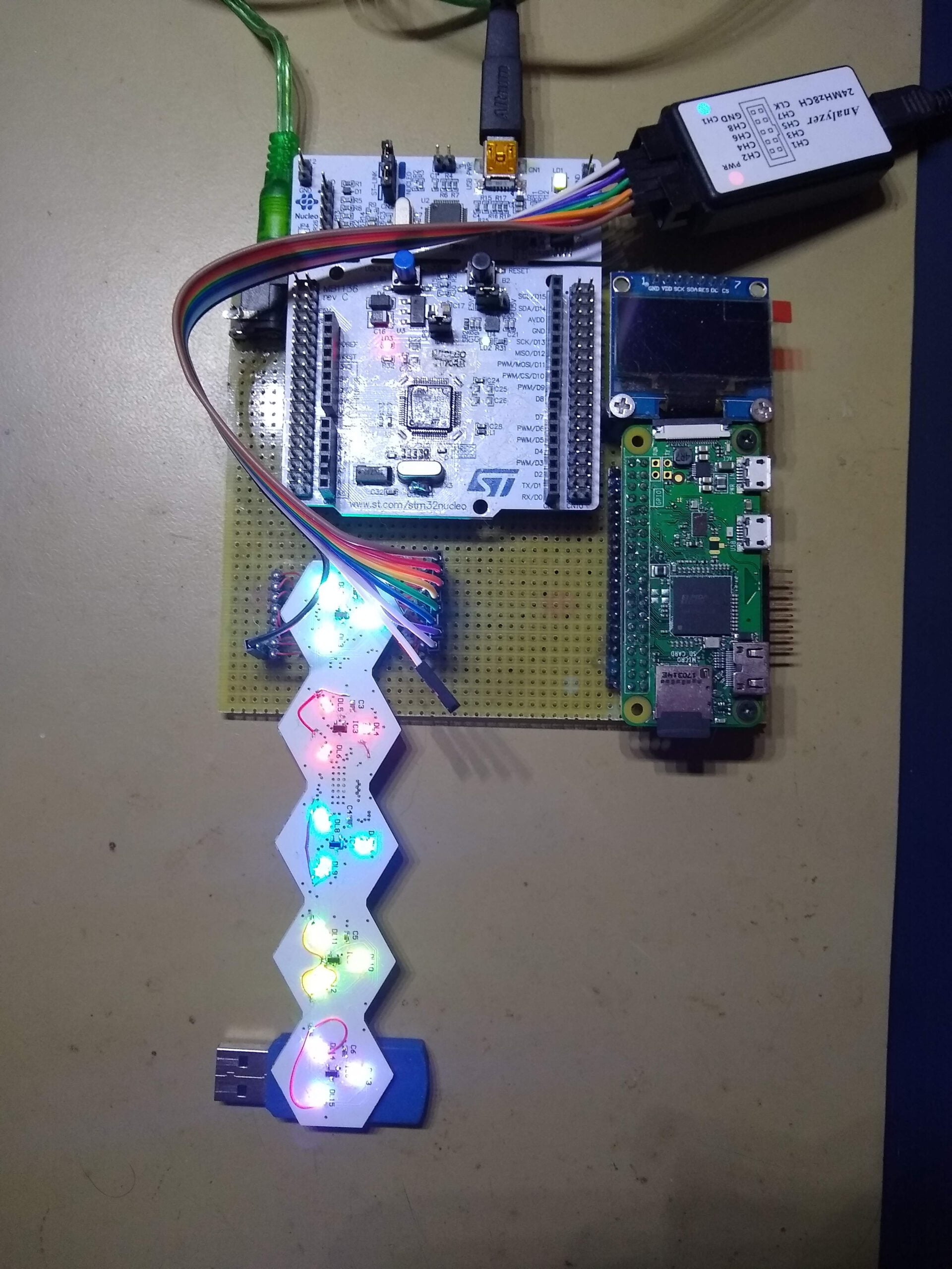
To start the prototype I used a development board NUCLEO-F103RB, which I already used in First prototype of the electronic board game Helvetios. This time I used the development board to program the circuit, using the connector that allows to program other circuit by using the SWD communication. This way I could connect to the electronic board game and debug the code for the led drivers and the Hall sensors:

Besides the development board I used a little 8 channel 24MHz logic analyzer. With this device and the software Pulseview from the Open Source project Sigrok is easy to see which signals are generating and check the correct addressing of the led drivers. Also you could decode some protocols as SPI and I2C, and is very useful to determine the refresh speed of the system.

When testing the code I also tried some led diffusers:


Finished the first PCB design of the Helvetios boardgame
These last months I’ve been finishing the design of what will be the first circuit of the programmable electronic boardgame Helvetios. It has been a little slow process, due doing it in my free time but mostly due doing it in only one circuit to save cost. In later designs I will continue with the concept of circuits of rows of cells, connected between them. This will allow bigger boards and with more and bigger cells.
The design of this boardgame have 91 cells, and it will be used to develop the control firmware. This software will manage the RGB lightning of the cells, the magnetic Hall sensors and the USB communication with the game master circuit.
Some screenshots of the finished circuit:
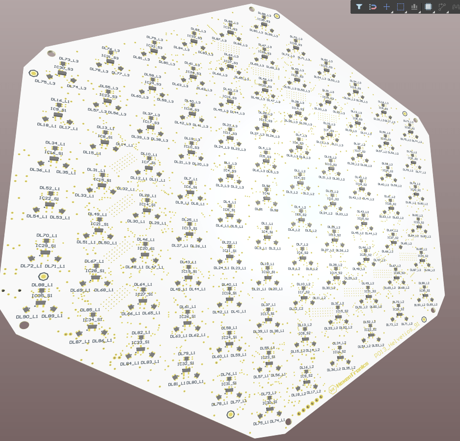
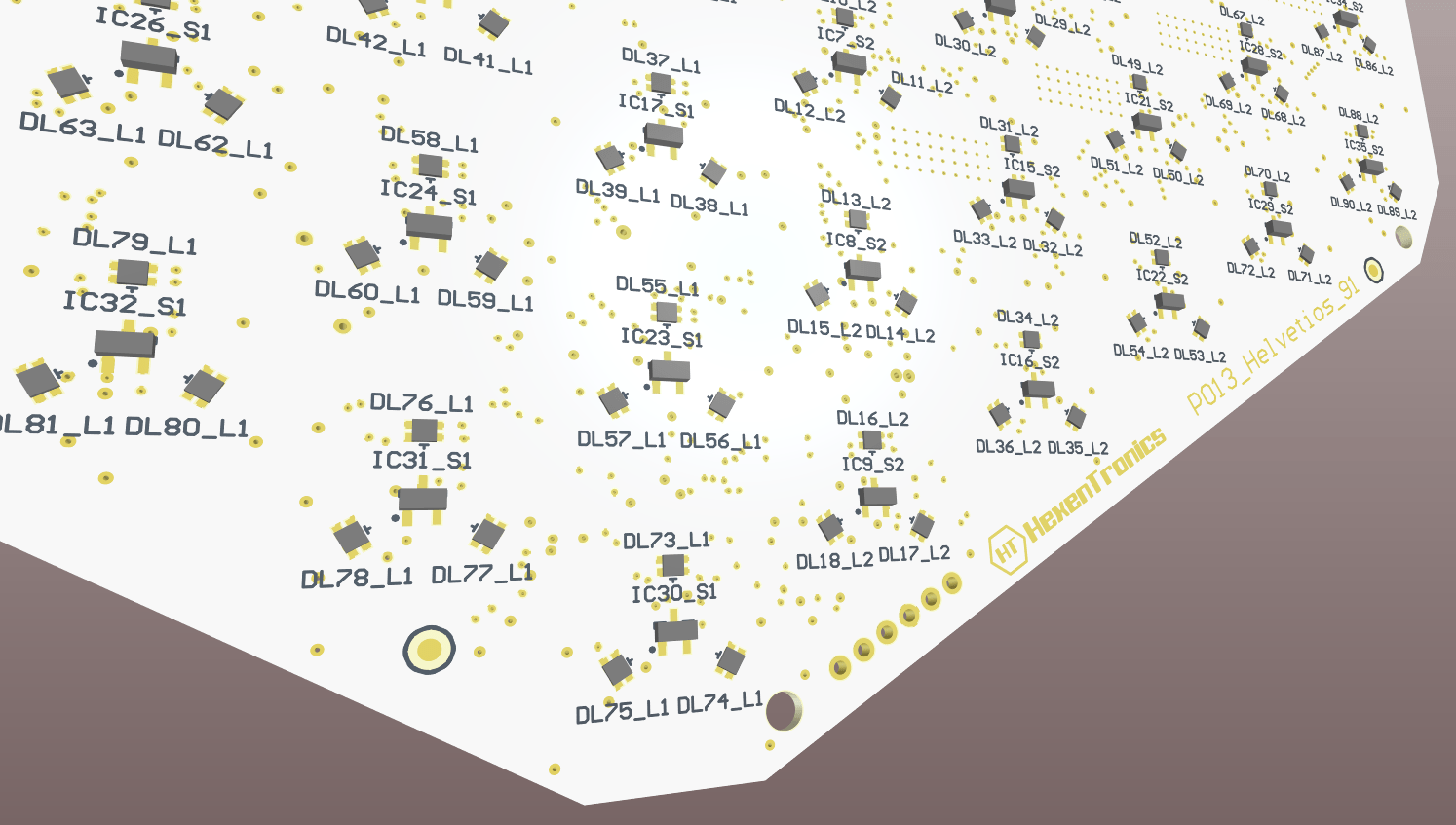

In the bottom layer there are the connectors. It has an input power supply connector, a micro USB to communicate with the game master circuit, and a power supply output connector to supply this other circuit.
Now starts the manufacturing process of the circuit, that will also be complicated due the lack of components supply situation. It’s very possible that I could not get some critical components like the led drivers or the microcontroller in all this year 2022. The lead time is 2023 for some of them. Also the fact that the circuit has components in both sides implies that not any factory could mount them, it needs two reflow processes to solder all the components.
I will use this this board circuit assembly time to develop the game master circuit, and make designs of the enclosure to house the circuits. So the next updates will be about how I’m doing designing this game master circuit, that will have a raspberry Pi Zero, an oled screen and a button interface so the user could choose the actions and movements. I will also advance some of the boardgame software, mostly the USB driver to test the communications with the Raspberry.
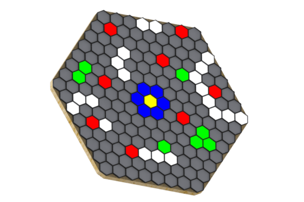
Addressing algorithms of hexagonal cells.
When I started the project Helvetios I thought how to map each cell individually, to give it an address to each one for when I developed the algorithms to interact with them. Mi first idea was to number the cells form the centre to the outside, making an spiral:

This way, when programming the addressing algorithms I could make an array of numbered cells. Each cell of that array would be a data structure: the colour, if it has ha piece over or not, the illumination effect and the numbers of the neighbour cells.
By this, when addressing a cell I could know which will be the next cell if I move to a certain direction.
Besides I would design the algorithms to calculate distances and ranges. To for example, light the cells to move around a piece, or to light a shooting line from a piece. I thought these algorithms could go through this cells structure and selecting the right neighbour cells based in the direction and the selected function. More or less I had all these though to, when designing the board control library, define these data structures.
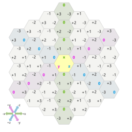
But this was before knowing the page Red Blog Games. In this brilliant page there are analysis of a lot of mapping techniques and how to calculate their addressing algorithms. It has a section of hexagonal maps https://www.redblobgames.com/grids/hexagons/ where it establish for types of addressing: Offset, Cube, Axial and Doubled. The coordinate system I’ll choose would be Cube and look like this:

Also defines the algorithms to change from a coordinate system to another, to calculate distances, lines, movements, ranges, intersections, obstacles, rotations, reflections, rings, spirals an line of sight.
So I already have all the needed theory to develop the library to interact with the board. This way I could design the data structures and functions to program the game algorithm.
This algorithm will allow at first a two player in turns game. Initially the two at the same board, but the target is to make an online game. Also will be possible to develop an AI to play against offline so, when the board will be fully developed, I will research for AI algorithms for gaming.
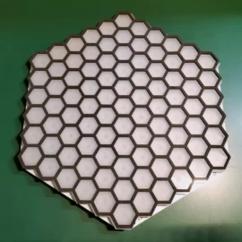
Lasercut gameboard
Returning to the design of the boardgame Helvetios after a long pause I’ve rethink about how I’ll made the first prototype. Instead of using several circuits interconnected, I’ve started to make a simpler design. To reduce costs of the circuits and the laser cuts I’ve taken an A4 sheet as a reference, what allows me to make prints of the board, buy cheap acrylic sheets and cutting in the laser of the makerspace I’m member.
In the board design I’ve included some buttons to interact in each game turn and to select the direction of the acction to make (movement, attack, defend, capture, etc…). Also I’ll include a little oled screen to show the actions to be selected and game parameters of the selected piece.

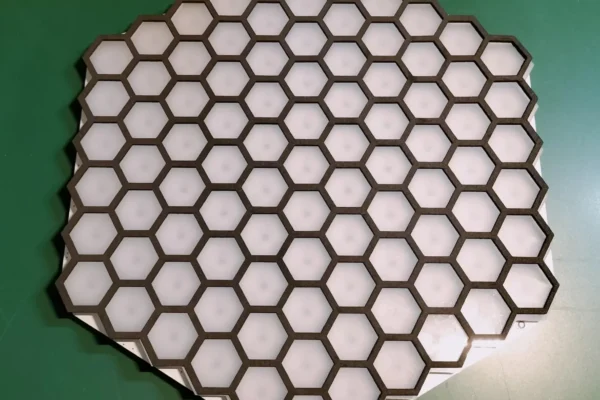
I’ve cut the upper part of the board in black acrylic so the hexagonal frame will be used to put the game pieces. Under it will be a translucent base that will serve as a led diffuser. In later designs it’s possible that each cell has its own diffuser instead of one for all the cells, depending on the results of the tests and if I achieve that not many light will leak form one cell to the next one. Surely I will have to isolate each cell under the diffuser and that each cell has its own hexagonal diffuser isolated form the others.
This is the result of the laser cut, in an 3mm black acrylic sheet and another translucent for the diffuser:

The next step is to design the circuit board that will be below the cells with leds and sensors (that it’s already in process) and another circuit with the oled screen and the buttons. I pretend that the circuit with the cells will be connected to the raspbery via USB. The circuit with the screen an the buttons will be connected directly to the raspberry using an SPI for the screen and the I/O inputs for the buttons.
First prototype of the electronic board game Helvetios
Circuit design:
The first prototype of the electronic board game Helvetios is the circuit that corresponds to one of the arms with sensors and leds. In each cell there is a magnetic Hall effect sensor and three RGB leds, what allows to detect if there is a piece or not over the sell and show the cell colour according to what is programmed in the game mechanics. This is the block design of this circuit:


In this prototype there is only 5 cells, but in the final design of the Helvetios board there will be 8 cells for each circuit. In the board will be 21 led circuits, which makes 169 cells counting the central cell. This size is selected so each leds circuit only will have one TLC5947 led driver, but could be increased in a future by connecting some of these divers in cascade. The distribution of these circuits in the board is showed here:
The schematics of this prototype has a only a few components: the Hall sensors DRV5032 ins SOT32 format, the led driver TLC5946, the RGB leds and the shift register SN74HC165:
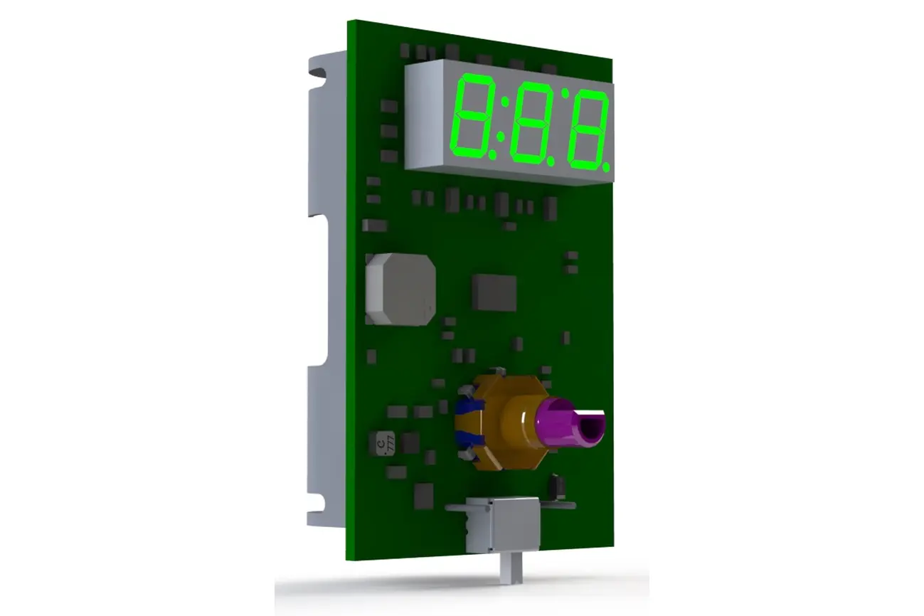
The PCB design and the 3D renders are showed here:
Development prototype:
To develop the control firmware I’ve used an evaluation board for Cortex M3 from ST NUCLEO-F103RB, actually it was a Cortex M0 board but I’ve repurposed it with a new microcontroller and adding an 8MHz quartz so the USB peripheral could work. I’ve in mind to modify it again to change the microcontroller for the STM32F103RC so I’ll have 3 SPI peripheral which will help me to control the three ‘branches’ of led circuits at the same time. It’s mounted in a bakelite board with a male connector for the led circuit and a Raspberry Pi Zero W with a little Oled screen. In the next phase of the project the microcontroller will be connected via USB to the Raspberry due it will include the high level software to control the game mechanics, the ‘game master’.

And to finish some examples of animations that could be achieved with this prototype:
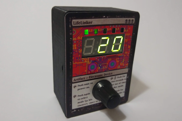
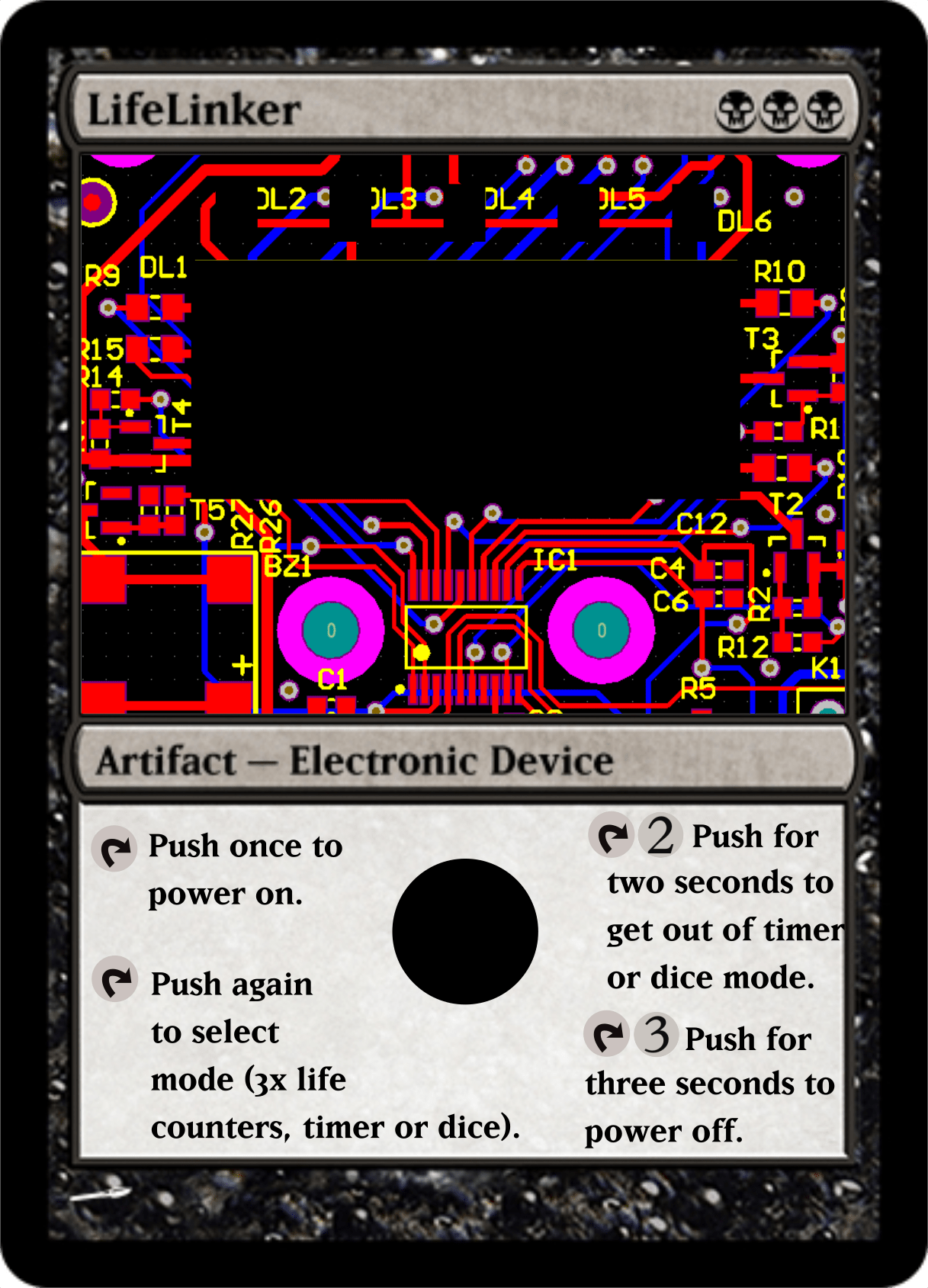
The LifeLinker design process:
To design the LifeLinker various design programs and manufacturingmethods were used, they will be briefed here. The Lifelinker design process were: schematic design, circuit design, 3D box design and microcontroller firmware programming.
For the manufacturing were used a 3D printer, a manual stencil printer, SMD oven for circuits and a laser cutter.
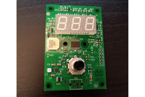
Circuit design:
The schematics and the PCB design were made using the software Altium Designer, due it’s what i use at work and I’m used to it, but I could used Eagle easily for this circuit.
One advantage to use Altium is that the component library that I use is made as an Acces database, what let me have more control over the components. I add various data about voltage, current, number of pads, supplier codes, datasheet links, stock and warehouse location, etc… This let me generate BOM’s with prices from suppliers (Farnell, Mouser, Digikey..) and their stock
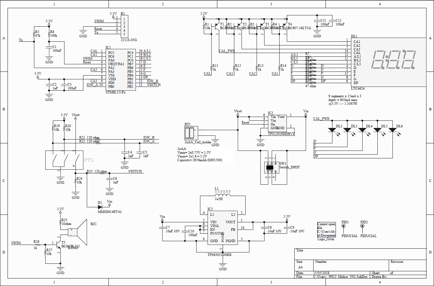
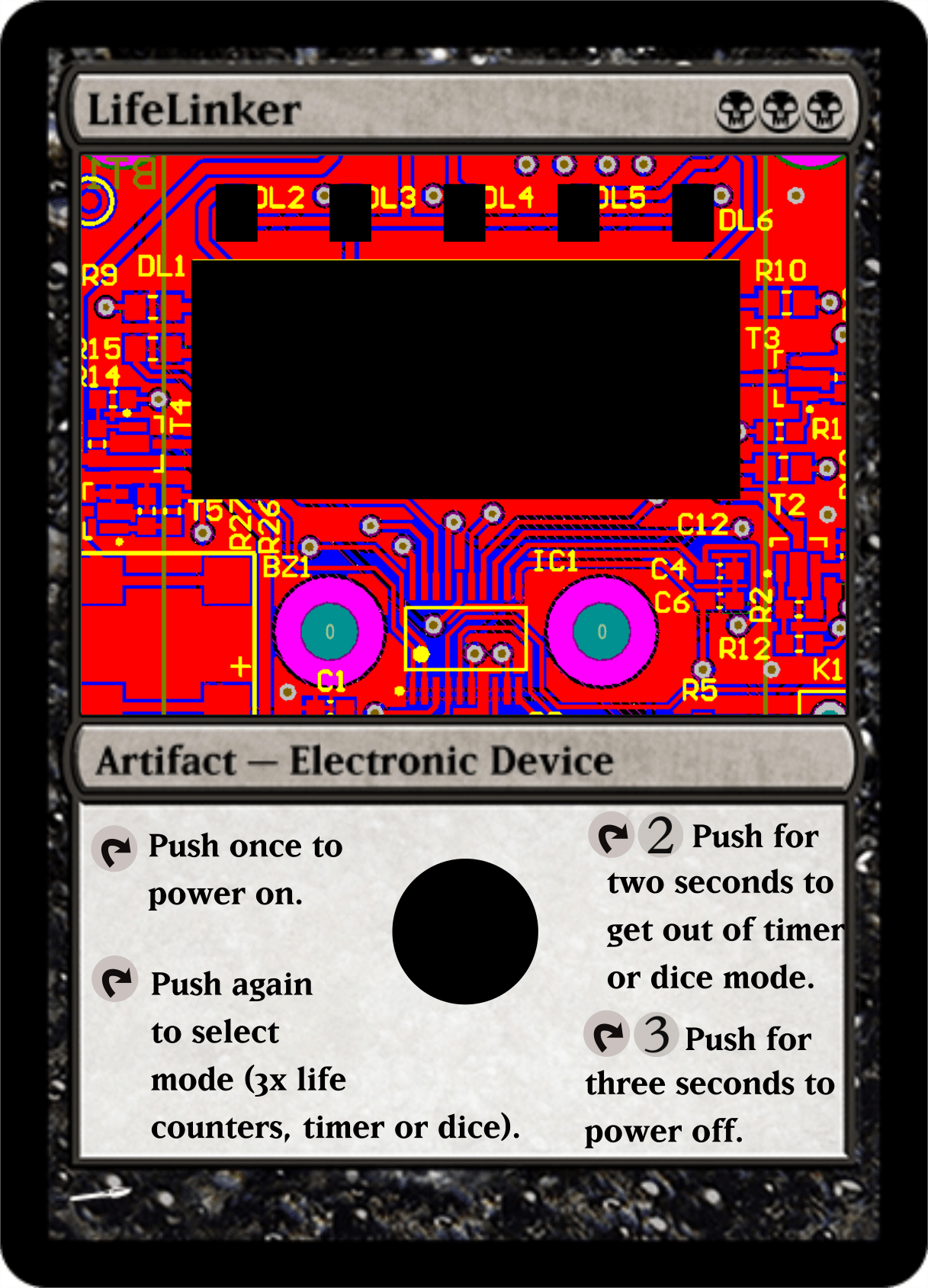
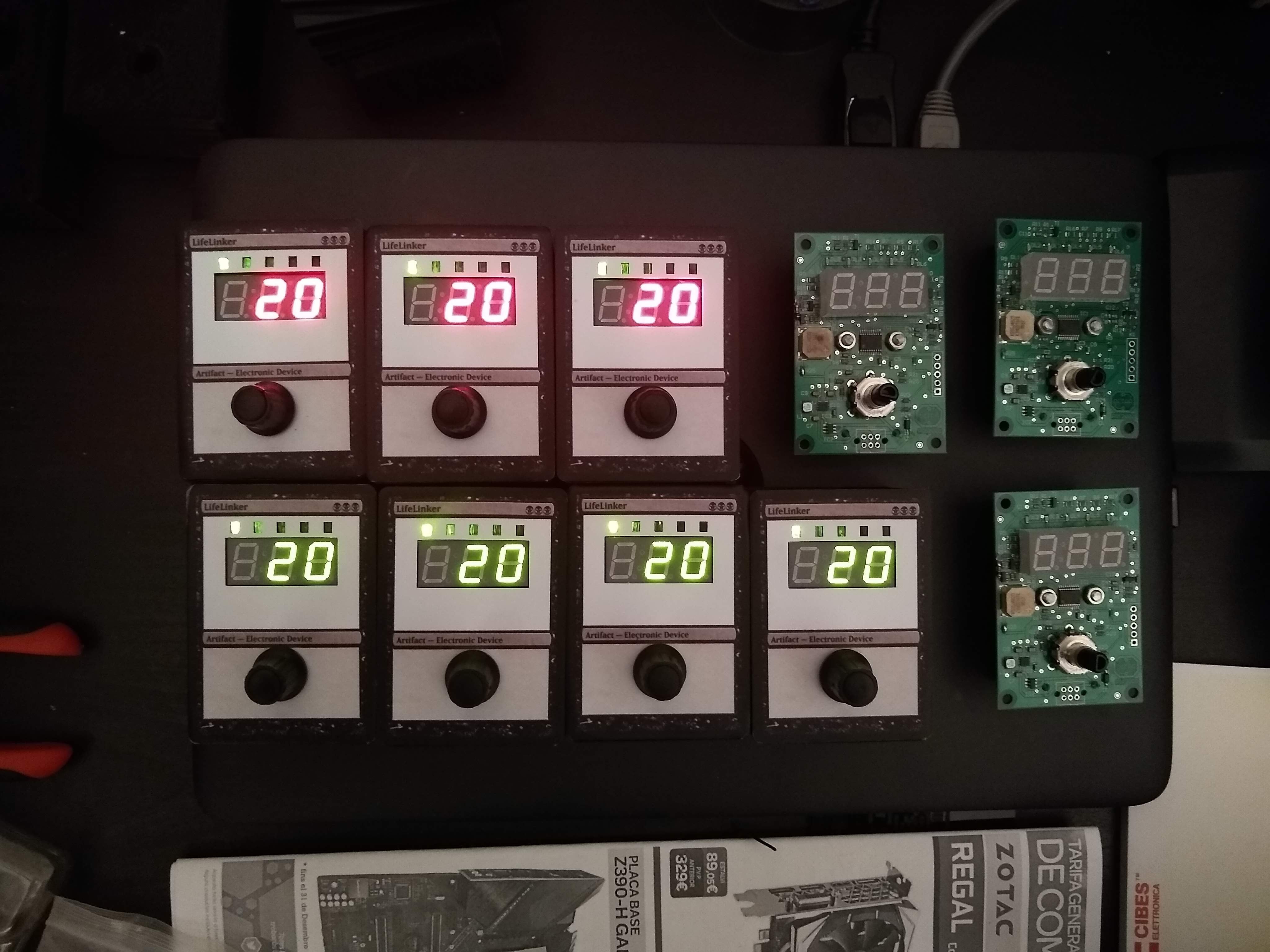
In the schematic we could see that it has a 8 bits microcontroller STM8L151, a rotative encoder, the power supply to generate 3V from the batteries, the 7-segments display with three digits, 5 leds to show the current mode and a buzzer. The microcontroller is fully maximized, it hasn’t a free pin, and from the 8kB of flash it has, the code uses 7.5kB
The PCB is simple, with two faces:
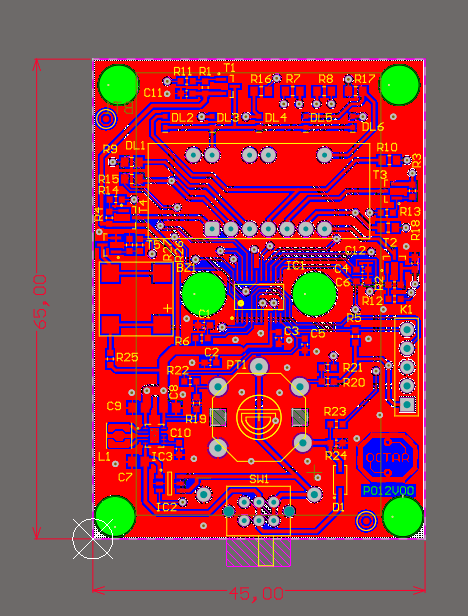
The prototypes were ordered to Elecrow with the solder stencil in 15x15cm. The cost of 10 PCB’s + shipping + stencil was only 30€, being a very low price. The solder stencil allows to make the soldering with a SMD oven and achieve a very professional result, also allows to mount some components with pads underside.
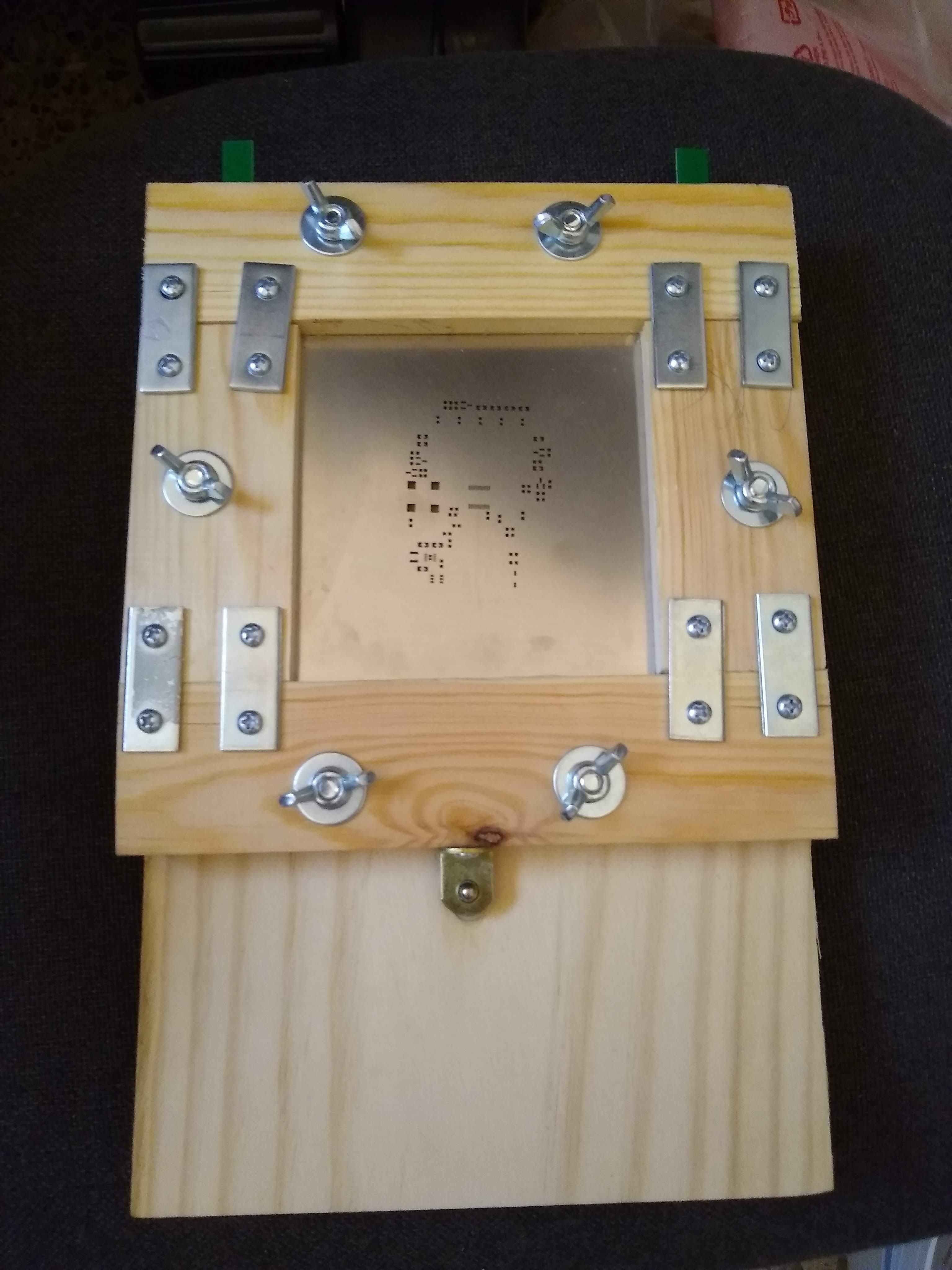
The solder stencil ordered with the PCB’s was used to mount all the MSD components. This stencil has 15x15cm and to solder all the circuits I made a wood framework that could be used in other projects:
Box design:
To make the box, the 3D design of the circuit was imported to Solidworks and the box was created over it. The box is made to be printed with a FDM 3D printer. The rear cover is laser cut and fits by sliding it in some slots in the box.
Front cover design:
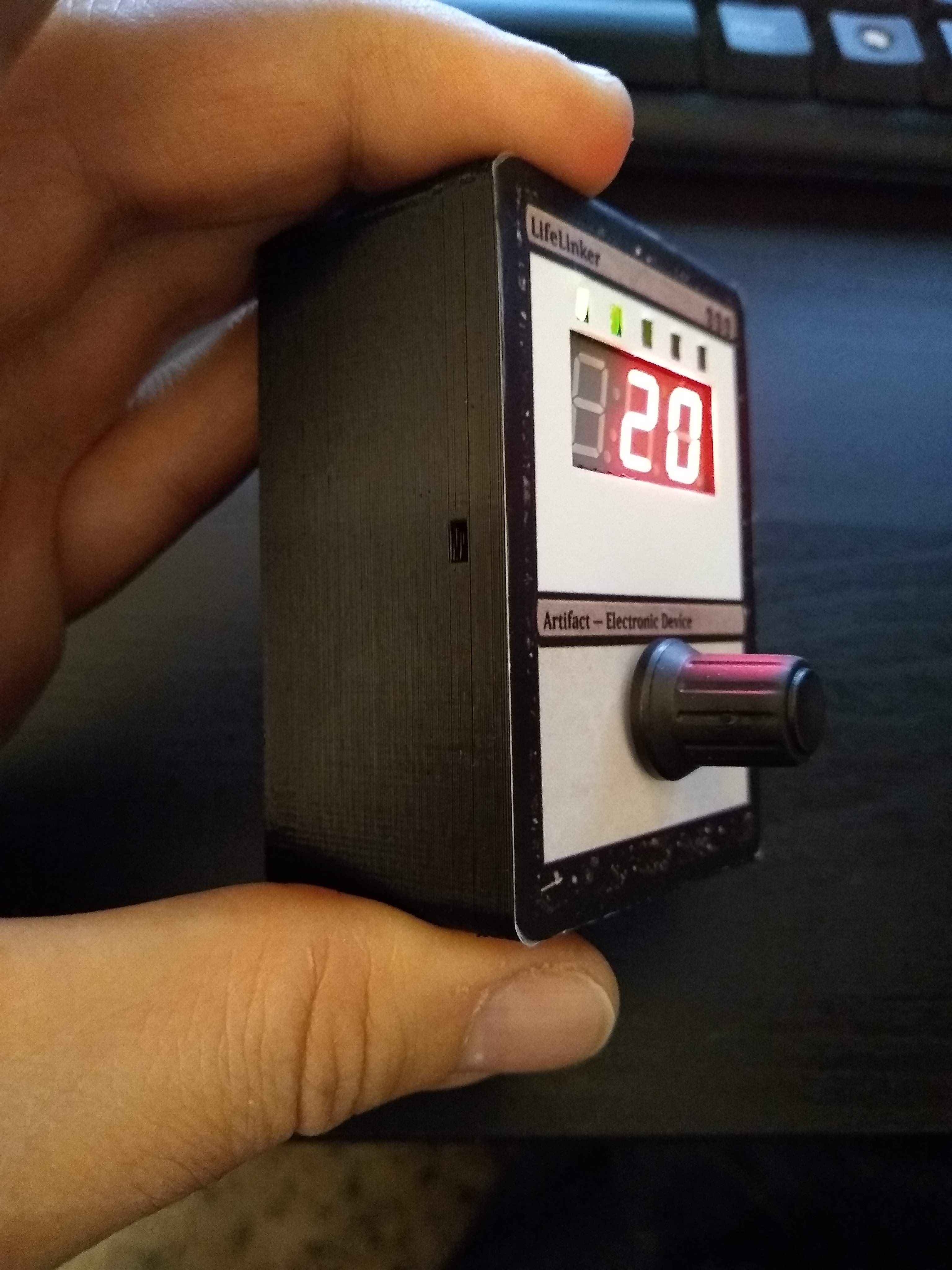
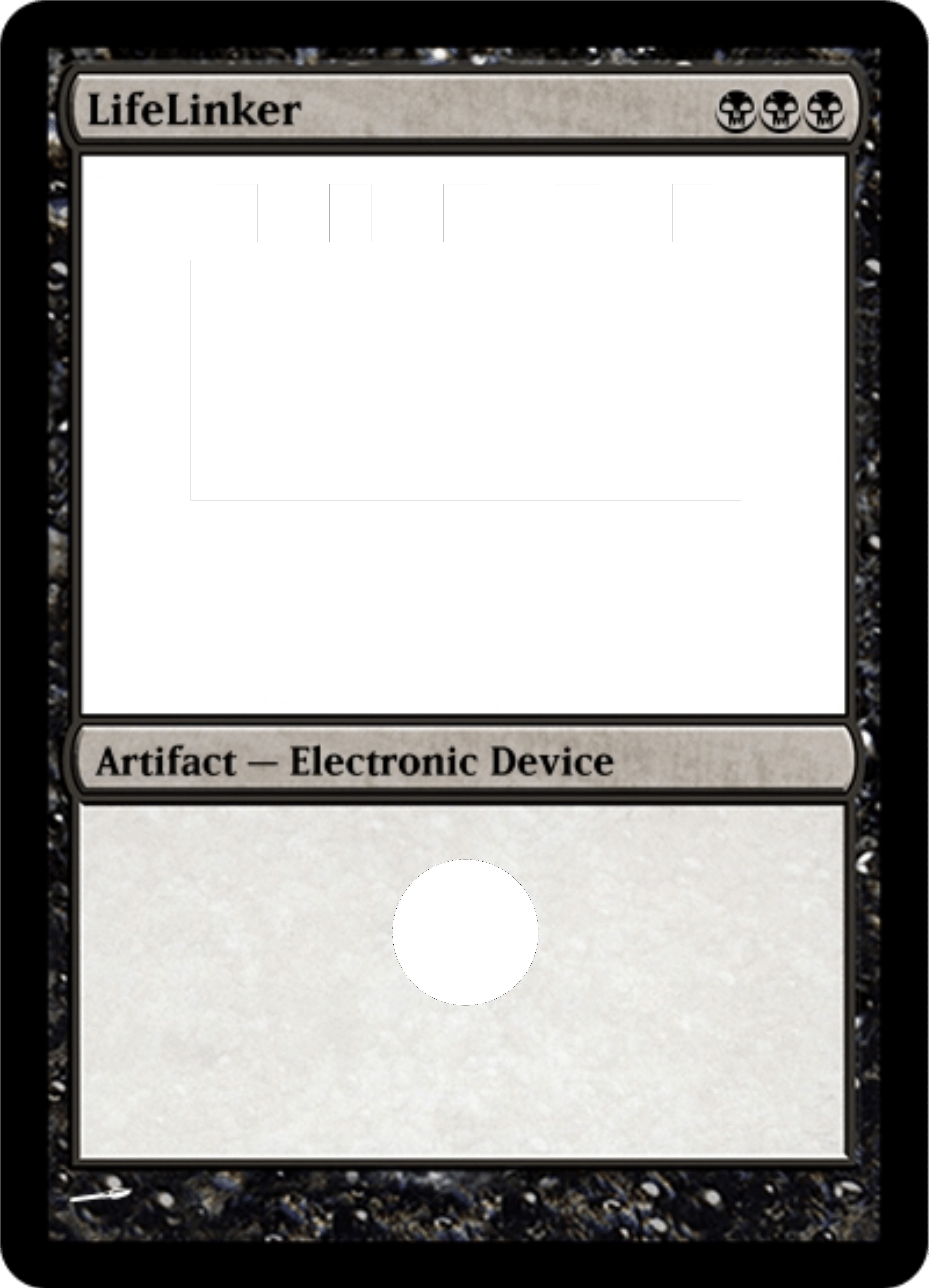
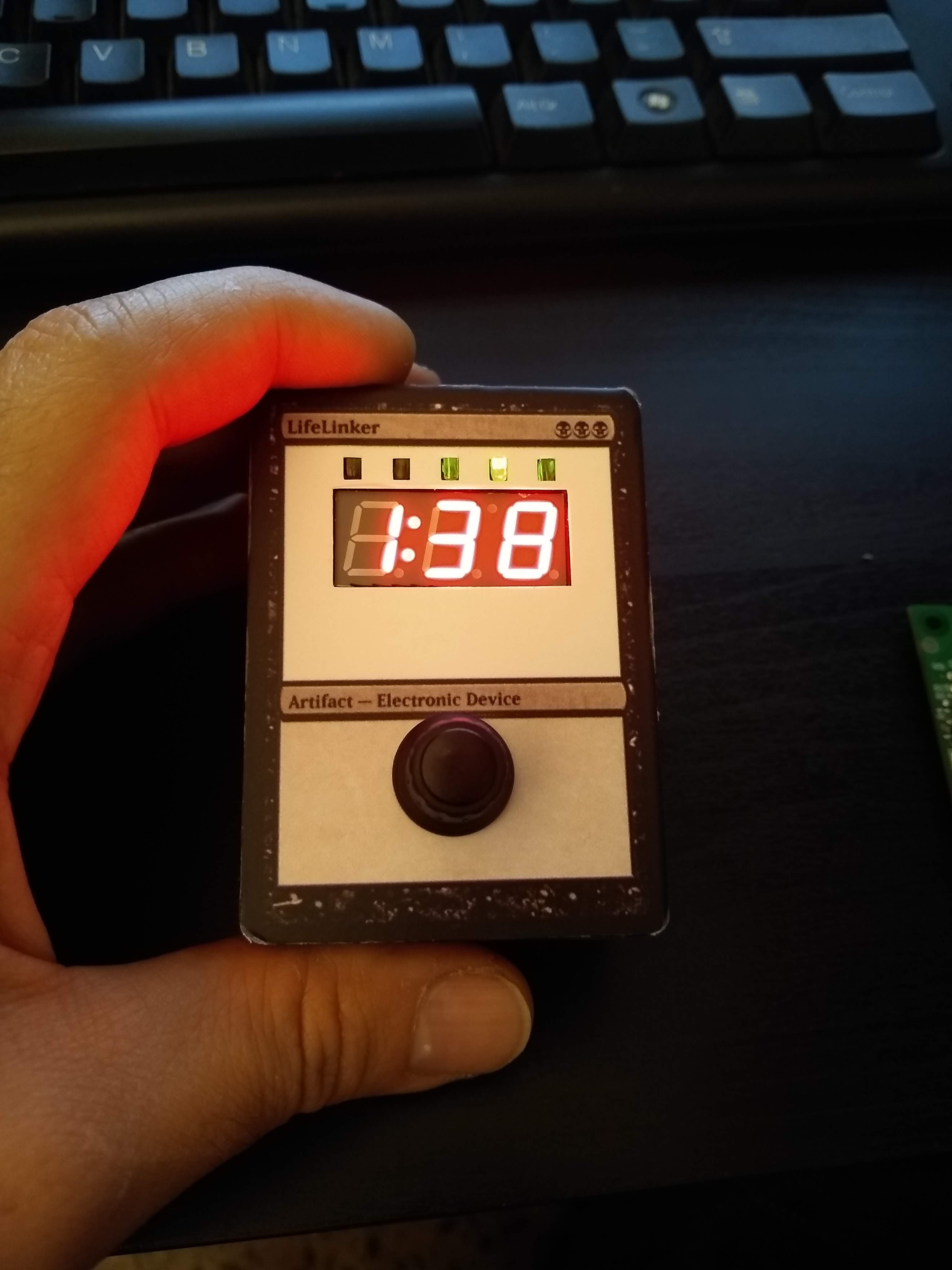
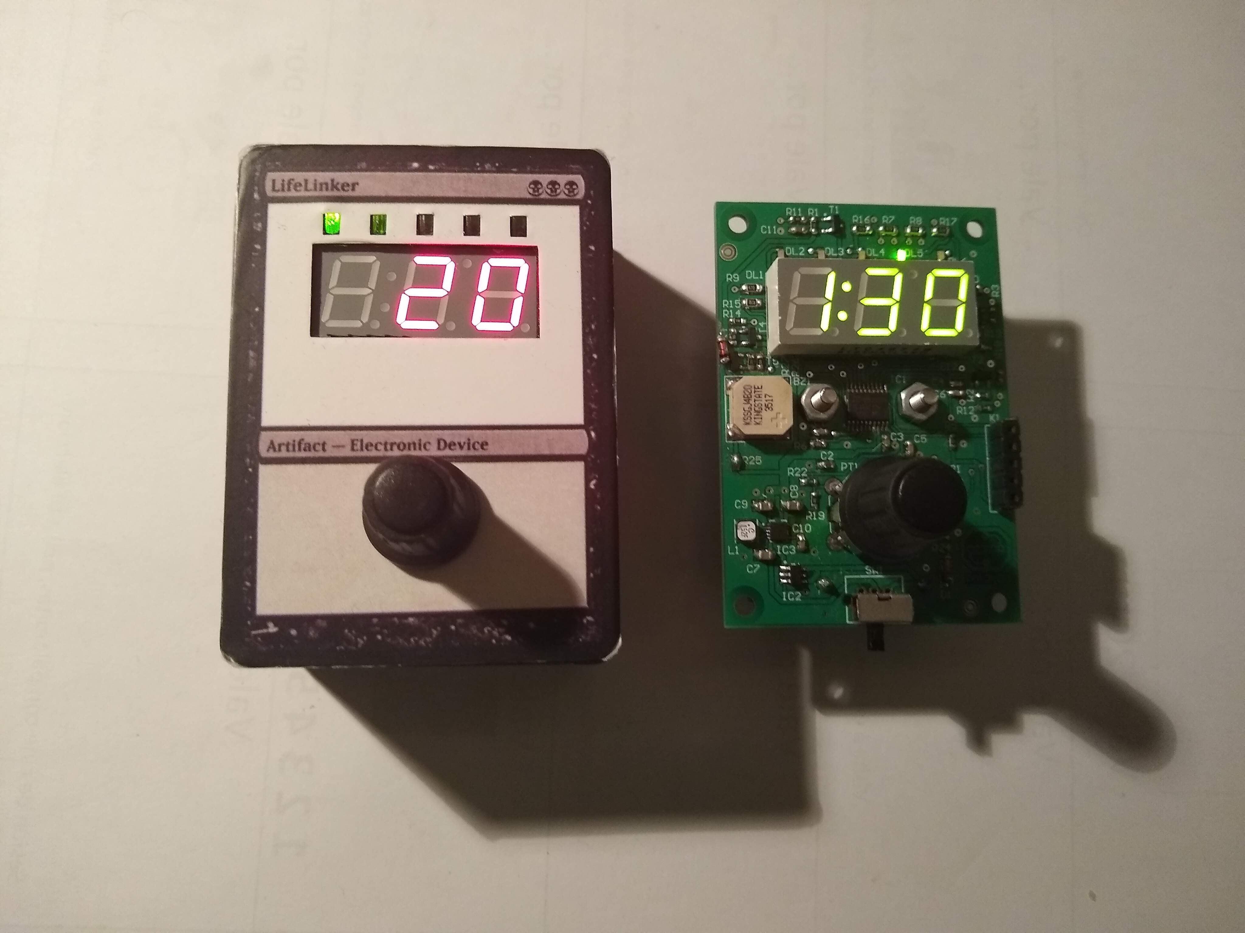
To make the front cover design I choose a Magic card, due this device is mainly thought to be used in this game, although is perfectly valid for many others. The box proportions are from a scale froma a Magic card, so I used the web Magic Card Maker to make a simply design and print it in adhesive vinyl. Later I redo the drawing adding text and the picture of the circuit in the card.
Programming the firmware:
The microcontroller is a 8 bits STM8L151F3 with 16MHz, 8kbytes Flash and 1kbyte RAM. To debug the code and program the prototypes I used the evaluation board STM8L-DISCOVERY and as compiler the CXSTM8 from Cosmic Software, it has a free license for the STM8 microcontrollers. As IDE I’ve used the ST one, STVD (ST Visual Develop). The code could be checked at Github, https://github.com/microhenrio/LifeLinker.

The beginnings
As a first post let’s explain why and how this web exists. I’ve been involved with electronics as far I can remember, studying it or working on it. I’ve worked making electronics projects for different companies for 15 years (hardware and firmware), mainly industrial and white goods electronics.
At one point I decided to make something by my own that could be easily made and developed with the tools I had in the moment, then I did a Bluetooth notifier (https://hackaday.io/project/28548-phone-bluetooth-notifier) with a very good result in the hardware and firmware design due I’m used to work with. I learned a little of 3D design and started to develop the app for it.
Unfortunately, Android Studio was too much for me and very frustrating to achieve a minimal app working, so I never had an MVP fully working. Also the feedback from the hardware accelerator companies was not good, I didn’t have a price for it or the costs for higher quantities, only the costs of the prototypes.
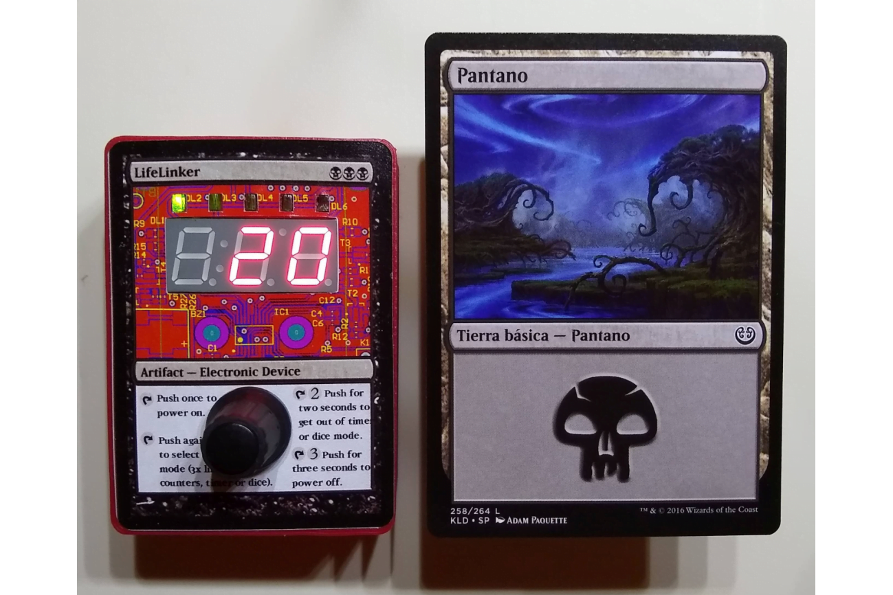
So, at that moment I decided to make the simplest electronic with purpose I could imagine. And then I remembered a very simple project I made some years ago at the Uni with a PIC microcontroller, to control the counting of life points in MTG (Magic the Gathering) games.
I decided to replicate it with a very low level electronics, but with the integration and cost-saving in mind. This way the project LifeLinker was born, mainly to experiment with the 3D design and printing, laser cutting, 2D drawings design, and taking care of the costs for all the process and looking for quotations to industrialize it in bigger quantities. Also I’ve find a way to sell them worldwide using Tindie, create the company image and set the web and social media channels. How I see it, this project has been used as a ‘seed’ to build something bigger over it.
The future projects will be try to follow this philosophy, to develop simple electronics to be used with existing games. Also, at the same time, to develop technologies to be used in these existing games or used to create our own electronic games. That’s the reason for existing of the blog section, to show the evolution of the projects in development.
The greatest adventure is what lies ahead.
J. R. R. TOLKIEN, The Hobbit
Today and tomorrow are yet to be said.
The chances, the changes are all yours to make.
The mold of your life is in your hands to break.
Latest Posts:
Assembly of the prototype of the ZeroDeck interface.
Assembly of the prototype of the ZeroDeck interface to control the electronic boardgame Helvetios. READ MORE

Interface ZeroDeck for RPI Zero
In this project I have been programming at the beginning an interface in GTK called GamMa. But the goal was to run that application on an RPI Zero 2W and for it to... READ MORE
USB communication with the boardgame and the GamMa program.
I’m already working again in the project after a long pause, but with renewed strength. I’ve mounted the Helvetios boardgame in a trainer that I made some time ago: a briefcase with a... READ MORE
Mounting the prototype of the 91 cells electronic board game
Finally I've gathered all the components and mounted the electronic board game Helvetios. READ MORE

Finished the first PCB design of the Helvetios boardgame
Finished the first PCB design of the electronic boardgame Helvetios. READ MORE
Addressing algorithms of hexagonal cells.
Analysis of coordinate systems and addressing algorithms to use in the electronic board game Helvetios READ MORE