


I have finished assembling the ZeroDeck interface to be able to control the game boards that I design. Separating the game board from the player interface allows me 2 things, first I can design the board independently of the interface and so you can control it by USB with a standalone module like the ZeroDeck or connect it to a PC or you could even connect it to a mobile and control the board from it. And second, the ZeroDeck interface can evolve independently of the board and serve for several different boards.
The current Helvetios board is just a prototype with which to design the development infrastructure and test the technologies involved. In the future the board will grow in size and number of cells, but first I have to test that everything works correctly, it is even possible that there are some rectangular or with another shape.
For now with this interface I can develop more easily. Until now I used an RPI4 to connect it to the board and with a GPIO pin expansion circuit I connected a keyboard and an SPI OLED screen. Now I have the GamMa game program running on an RPI Zero 2W that controls the screen, reads the buttons and turns on the LEDs that will indicate the player’s status/turn and what phase of the game they are in. The assembled circuit is as follows:
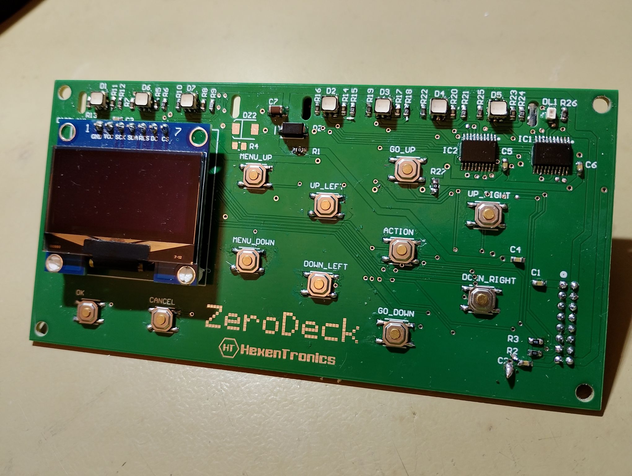
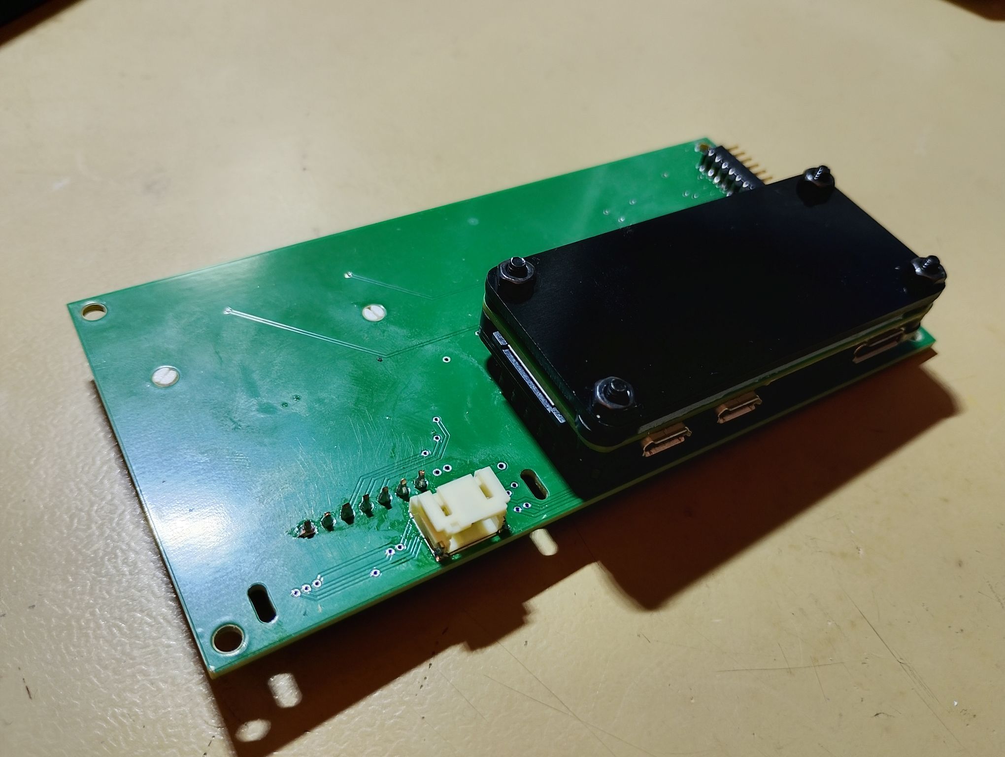

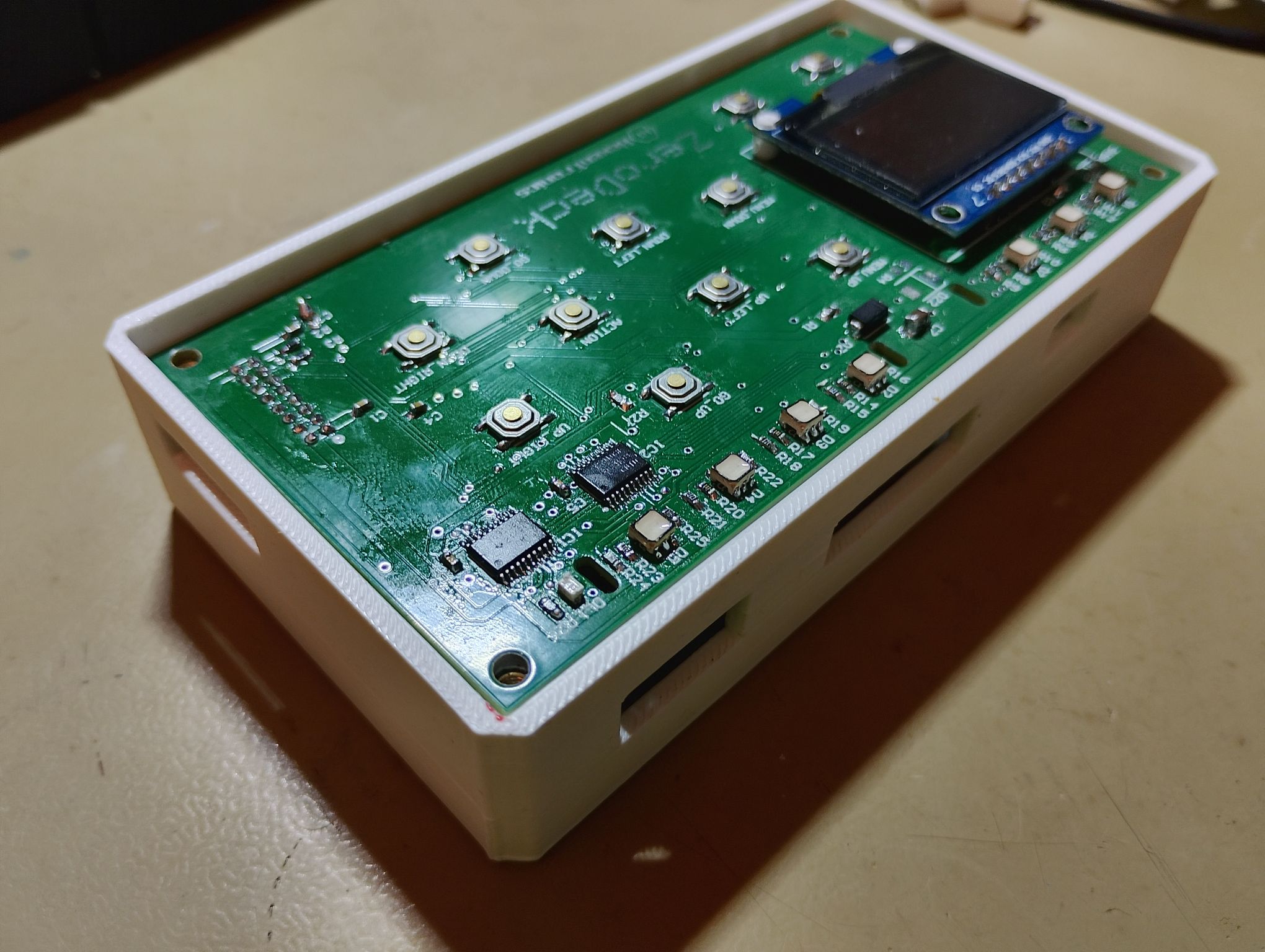
The Zerodeck’s connector openings allow access to the RPI Zero’s microUSB and mini HDMI connectors. It also has its own power connector, since it can be fed directly from the boardgame with a cable designed for it and thus only have one power supply for the whole set. The circuit has another side connector that will allow it to be expanded and tested with other circuits. The idea is to be able to connect a second or several identical modules for each player, and having only one ‘Master’ module with the RPI Zero that controls the rest of the interfaces. It also has to be used to test other modules that I have in mind, such as an NFC tag reader so that each piece can save its statistics and characteristics, and perhaps a small sound module for some effects.
For now, the first tests are as that:
The use of an RPI Zero has a handicap and that is development. In order to develop the GamMa application for control of the board I have been using VSCo remotely in the RPI4 with good results to interact, debug and compile. Not so with the RPIZero, because it does not have an ethernet connection and through Wi-Fi VSCode’s remote mode does not seem to work very well, with multiple interruptions. Debug and compile also don’t work very fast in the RPIZero, so I keep developing in the RPI4 with VSCode and when I have a change ready I synchronize them through Github in the RPIZero, where I recompile it, since they have different cores. For now I’ll have to develop like this, maybe I’ll try automating it a little more or using NFS.
